


Page 11
© Multilink Inc. 2021
•
All Rights Reserved
Do
cumen
t N
o. 965-088-10I
nstall
INST
ALL
ATION
Cop
yrigh
t © 2021 Multilink I
nc
. A
ll righ
ts r
eser
ved • Sp
ecific
ations subjec
t t
o change without notic
e • Re
v. 11/16/2021
Do
cumen
t N
o. 965-088-10I
nstall
4.22 Attach Splice Tray
For kits without the metal plate, use the
supplied screws. Secure the splice tray to the
Optima™ U base using the appropriate holes.
Installation (Cont.)
4.21 Splice Tray Routing
Place the completed splice tray within the
Optima™ U base. Route the branched off buffer
tube(s) accordingly with how the pigtail slack will
be routed.
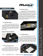
4.19 Splice Input Fiber to Pigtail
Following your splicers manual, splice the
appropriate number of fibers from the branched
off buffer tube to that of the provided or separately
purchased pigtail.
(Multilink is NOT responsible for
any damages or drastic light loss if splicing is not
performed by a trained technician following the
necessary instructions.)
Splicing Buffer Tube to Pigtail
4.20 Add Velcro
If metal plate is included with this kit,
slide velcro through metal plate slots.


