3. Ensure the new network settings chosen for the VF-9000
frame are compatible with the network the VF-9000 is to
be employed in. The computer used for monitoring the VF-
9000 frame must be on the same subnet. Contact your IT
Department if necessary.
4. Verify the IP address entered is correct and then click
the “Save IP” Button. This IP address will be stored in non-
volatile memory on the frame controller card.
5. The new IP address will not take effect until the IP Address
DIP switch is changed to the User IP address position. If the
DIP switch is already in the User IP position, a toggle of the
User IP position switch from off to back on again may be
required for the new address to take effect.
6. Enter the new IP address in the address bar of a web
browser and hit enter to verify the new IP address.
To use DHCP to automatically assign network settings:
Network settings for the VF-9000 frame may be
automatically configured via a DHCP server on the
facility network. This method would be recommended
for advanced users only as there is no way to display
the DHCP assigned address on the frame itself.
To configure the network settings via DHCP:
1. Connect the VF-9000 frame to your network using an
Ethernet cable.
2. Power up the VF-9000 frame.
3. Set the DIP Switch position 1 to ON to specify DHCP
configured settings.
Physically identifying a VF-9000 frame in a facility:
On the rear of the chassis, there is an ID LED which can be
used to help identify the location of a particular VF-9000
frame. The Frame ID LED button in the Ethernet Settings Box
of the Web page allows you to turn this LED ON or OFF. When
turned ON, the LED on the chassis will blink.
Web page status monitoring
You can monitor the status of all the cards in your VF-9000
frame via a Web page dashboard that is served from the
network controller card within the frame. This Web page is
accessed through any web browser by simply entering the
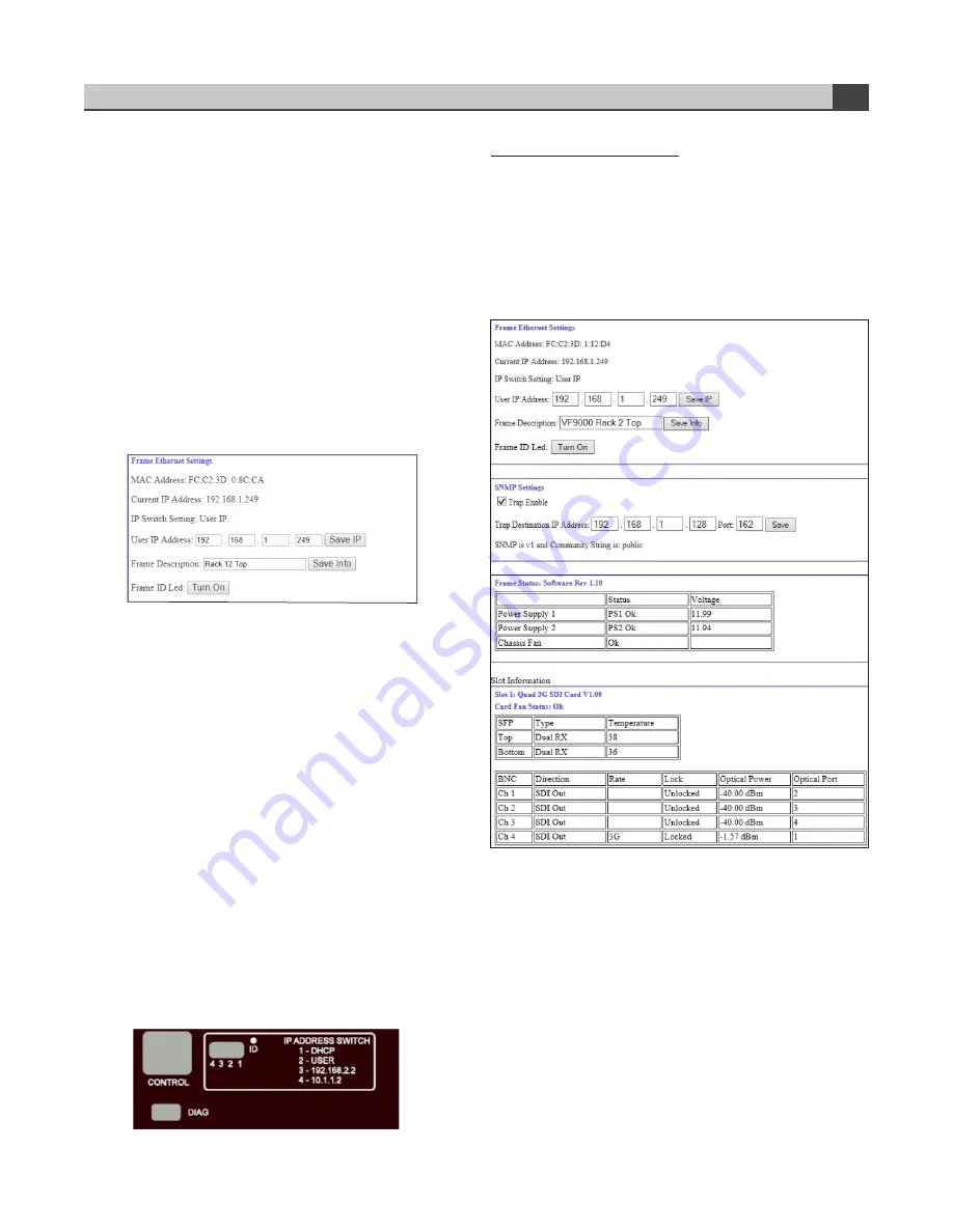
IP address of the frame in the address bar. Shown below is a
screen capture of the Web page from Internet Explorer.
The Web page is grouped into two areas. At the top is a
box that contains the frame’s current network settings
information. Below that, there are individual boxes which
display the information pertaining to the video cards that are
installed in the chassis.
Instruction Manual, VF-9000 Series
FEATURES & OPERATION
4
Ethernet settings box on web page
Rear panel showing network settings and ID LED


