


MEASURING METHOD
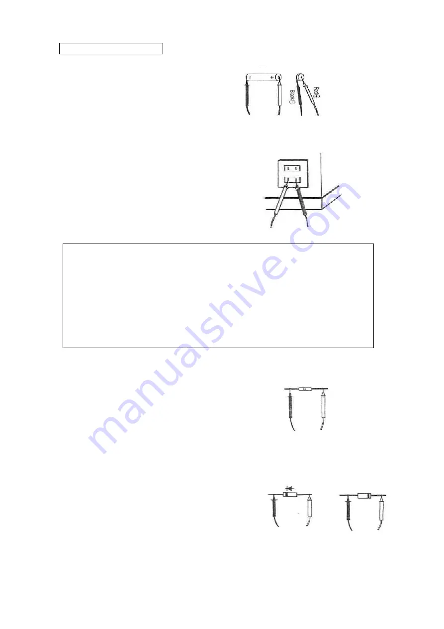
1. DC VOLTAGE (DCV)
1) Set the position of rotary switch from OFF to DCV (… sign will be displayed).
2) According to the drawings,
red test lead contact to
○
+
polarity
battery etc. and black one to
○
-
.
3) Read the voltage value on the display. (Can measure up to 500V automatically).
2. AC VOLTAGE (ACV) TRUE RMS
1)
Set the rotary switch position to V and press once the select key to chose
「~」
.
2)
According to the drawings, insert
the test leads to the outlet , etc. to
be measured. (In case of ACV measurement,
red or black test lead and polarity of
○
+
or
○
-
are no concern).
3)
Read the voltage value on the display.
(Can measure up to 500V automatically).
△
!
WARNING
1. Do not apply the input signal more than max. rated input voltage (500V).
2. During measurement, do not change rotary switch position.
3. Do not hold and or touch the nearer position of test leads to the tip over collar
during measurement.
4. POSSIBLE ELECTRIC SHOCK
Confirm that there is no damage in the isolated wire of test leads before
connecting. In case of out of order, stop the operation and repair them.
5. POSSIBLE DAMAGE & FIRE HAZARD
Connect test leads firmly, the wrong connection may cause spark.
3. RESISTANCE (
Ω
)
1) Set the rotary switch position to
Ω
.
・
)))
➔
+ and chose
Ω
by select key.
2)
According to the drawing, contact test leads
to the both sides of the resister to be measured.
(It does not matter about
○
+○
-
polarity).
3)
Read the resistance value on the display.
(Can measure up to 40M
Ω
automatically).
4. DIODE TEST (
➔
+ )
1) Set the rotary switch position to
Ω
.
・
)))
➔
+ and chose
➔
+ by select switch.
2)
In case of measurement for the forward voltage,
contact the test leads as in the way of drawing. Forward Voltage Backward
Voltage
The measuring range of general diode is between
➔
+
0.4 and 0.7V.
3)
In case of the backward voltage, contact the test
leads according to the drawing. In this case, the
display becomes OL generally.
5. CONTINUITY (
・
))) )
1) Set the rotary switch position to
Ω
.
・
)))
➔
+ and chose
➔
+ by select switch.
2)
Contact the test leads to the two point to be checked for continuity.
3)
The continuity resistance value will be displayed and the beep sounds in case of less
than approx. 20
Ω
.


