


Temposonics
®
E-Series CANopen
Operation Manual
13
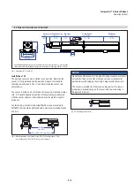
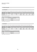
4.4 Styles and installation of E-Series EH
Controlling design dimensions are in millimeters and measurements in ( ) are in inches
Unless otherwise stated, apply to the general tolerances according to DIN ISO 2768-m
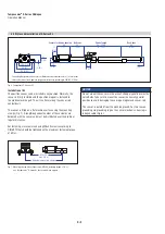
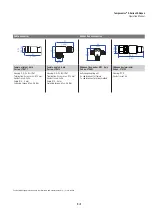
Fig. 8: Temposonics
®
E-Series EH
Magnet
Ø 34
(Ø
1.34)
AF 34
Sensor electronics housing
48
(1.89)
13
(0.51)
Dead zone
63.5
(2.5)
Stroke length
50…2540
(2…100)
8
(0.31)
Sensor rod
Type: Ø 7 ± 0.10 (Ø 0.28 ± 0.01)
Type: Ø 10 ± 0.13 (Ø 0.39 ± 0.01)
Null zone
51
(2)
PUR cable:
24.3 (0.96)
Teflon
®
cable:
26 (1.02)
Cable length
60
(2.36)
14
(0.55)
Threaded flange
Type: M18×1.5−6g
or
Type: ¾"-16 UNF−3A
5 pin
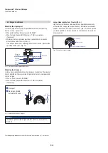
Installation of EH
The rod-style version has been developed for direct stroke
measurement in a fluid cylinder.
Mounted on the bottom of the piston, the ring magnet travels over
the rod contactlessly and marks the position exactly through the
rod wall – independent of the hydraulic fluid.
Hydraulics sealing
The sealing via a 15.3 × 2.2 O-ring in the undercut is possible (Fig. 9).
A screw hole based on ISO 6149-1 (Fig. 10) must be provided.
• The flange contact surface must be seated completely on the
cylinder mounting surface.
• The cylinder manufacturer determines the pressure-resistant gasket
(copper gasket, O-ring, etc.).
• The position magnet should not grind on the rod.
• The plunger borehole (Ø 10 mm rod: ≥ Ø 13 mm (≥ Ø 0.52 in.) /
Ø 7 mm rod: ≥ Ø 10 mm (≥ Ø 0.4 in.)) depends on the pressure
and piston speed.
• The peak pressure should not be exceeded.
• Protect the sensor rod from wear using suitable constructive
measures.
With M12 connector
With cable outlet
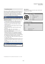
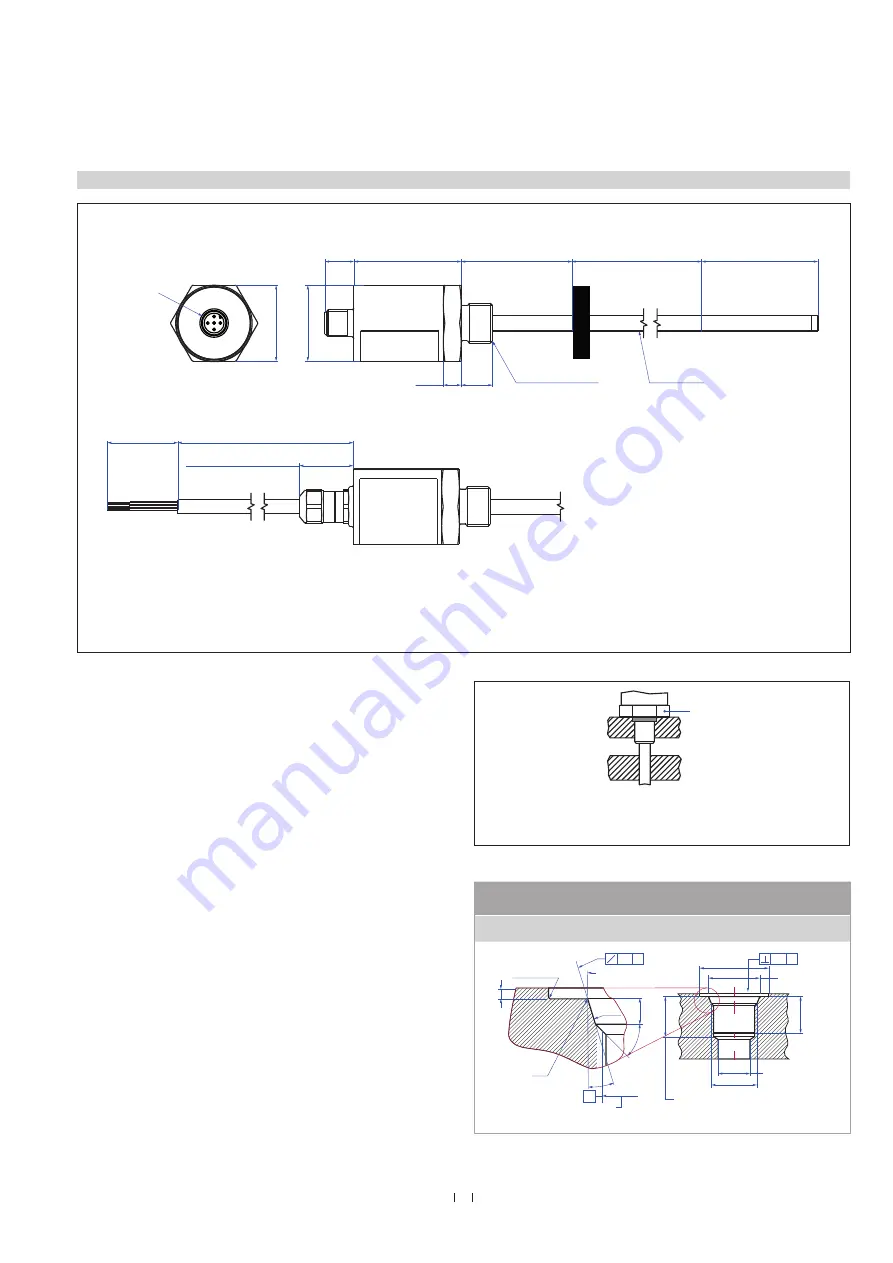
Fig. 10: Notice for threaded flange M18×1.5-6g lean on DIN ISO 6149-1
Thread
(d
1
×P)
d
2
d
3
d
4
d
5
L
1
L
2
L
3
L
4
Z°
M18×1.5 55 mm 13 mm /
10 mm 24.5 mm 19.8 mm 2.4 mm 28.5 mm 2 mm
26 mm
15°
This dimension applies
when tap drill cannot
pass through entire boss
Thread (d
1
×P)
(Reference size)
Applies at Ød
4
A
R 0.4 max.
L
3
L
1
45° ±5°
Ra 3.2
Ød
5
Ra 3.2
Ød
2
Ra 0.2
Ra 0.1
Pitch diameter
Z°
L
2
L
4
A
0.2 A
0.2 A
Ød
3
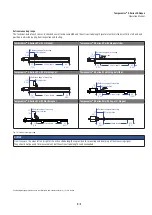
Fig. 9: Sealing via O-ring 15.3 × 2.2 in the flange undercut
max.
50 Nm
Sealing via O-ring
15.3 × 2.2
(0.6 × 0.09)
in the flange undercut