SineWave Nexus™ Technical Reference Manual 380V - 600V
9
Form: SWN-TRM-E February 2020 REV. 001
Common Mode Voltage Waveforms
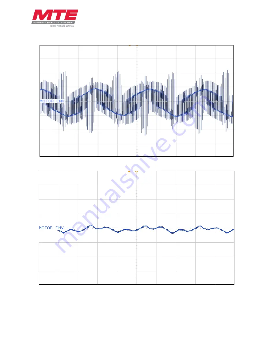
Figure 3-3: Common Mode Voltage without SineWave Nexus
Figure 3-4: Common Mode Voltage with SineWave Nexus
Страница 1: ...AL WARNING High Voltage Only a qualified electrician can carry out the electrical installation of this filter Quick Reference Performance Data Pages 5 10 Selection Guide Pages 11 16 Installation Guide...
Страница 2: ...This page intentionally left blank...
Страница 3: ...S 8 COMMON MODE VOLTAGE WAVEFORMS 9 ALTITUDE DERATING 10 MOTOR FREQUENCY DERATING 10 4 HOW TO SELECT 11 SELECTION GUIDE 11 UNDERSTANDING THE SINEWAVE NEXUS PART NUMBER 12 SINEWAVE NEXUS 380 480V 60HZ...
Страница 4: ...Diagram 25 Figure 5 5 DC Bus Connected Configuration 26 Figure 5 6 Ground Connected Configuration 26 List of Tables Table 3 1 Performance Specifications 5 Table 3 2 Filter Efficiency Watt Loss SineWav...
Страница 5: ...gh Voltage Warning warns of situations that dangerously high voltage is involved Failure to use proper precautions may lead to serious injury or death WARNING General Warning warns of situations that...
Страница 6: ...must be followed Injury or death may result if safety precautions are not observed The filter must be grounded with a grounding conductor connected to all grounding terminals Modular filters must hav...
Страница 7: ...efully inspect the shipping container for damage that may have occurred in transit Then unpack the filter and carefully inspect for any signs of damage Save the shipping container for future transport...
Страница 8: ...ll provide protection against contact with the enclosed equipment Type 2 NEMA IEC IP20 Enclosure Are designed for indoor use and will provide protection against contact with the enclosed equipment and...
Страница 9: ...al performance achieved 4kHz Inverter Operating Frequency 6Hz to 75Hz 75Hz to 120Hz with derating Maximum Ambient Temperature 40C to 60C Modular Filter 40C to 55C Enclosed Filter 40C to 90C Storage In...
Страница 10: ...oss SineWave Nexus 380 480V 60Hz Maximum Output Amps RMS Filter Current Rating Amps RMS Efficiency Typical Power Dissipation Watts 2 98 40 33 3 98 50 36 5 98 60 55 12 98 90 102 17 98 90 148 22 98 90 1...
Страница 11: ...Efficiency Watt Loss SineWave Nexus 600V 60Hz Maximum Output Amps RMS Filter Current Rating Amps RMS Efficiency Typical Power Dissipation Watts 5 98 50 76 12 98 70 157 17 98 70 213 22 98 90 243 27 99...
Страница 12: ...neWave Nexus Technical Reference Manual 380V 600V Form SWN TRM E February 2020 REV 001 8 Voltage Waveforms Figure 3 1 Output Voltage before SineWave Nexus Figure 3 2 Output Voltage after SineWave Nexu...
Страница 13: ...s Technical Reference Manual 380V 600V 9 Form SWN TRM E February 2020 REV 001 Common Mode Voltage Waveforms Figure 3 3 Common Mode Voltage without SineWave Nexus Figure 3 4 Common Mode Voltage with Si...
Страница 14: ...eWave Nexus Technical Reference Manual 380V 600V Form SWN TRM E February 2020 REV 001 10 Altitude Derating Figure 3 5 Altitude Derating Curve Motor Frequency Derating Figure 3 6 Motor Frequency Derati...
Страница 15: ...possible longer applications Voltage Input voltage from 380V 600V See Table 3 1 Performance Specifications p5 for specification Current Rating Support for 2 Amps 160 Amps Switching Frequency Support f...
Страница 16: ...orm SWN TRM E February 2020 REV 001 12 Understanding the SineWave Nexus Part Number SWN X _ _ _ _ X SineWave Nexus Type M Modular G General Purpose NEMA 1 2 W Weather NEMA 3R Current Rating 0002 is 2...
Страница 17: ...3 5 SWNM0005D 19 8 2 x 6 9 x 4 8 7 5 x 3 0 4 3 x 9 4 x 5 1 5 5 7 5 12 SWNM0012D 32 10 2 x 8 8 x 5 8 7 5 x 3 0 4 3 x 9 4 x 5 1 7 5 10 17 SWNM0017D 51 13 1 x 11 0 x 6 6 7 5 x 3 0 4 3 x 9 4 x 5 1 11 15 2...
Страница 18: ...50 65 SWNG0065D 174 33 9 x 18 3 x 20 9 55 75 110 SWNG0110D 221 33 9 x 18 3 x 20 9 75 100 130 SWNG0130D 255 33 9 x 18 3 x 20 9 90 125 160 SWNG0160D 385 51 3 x 27 7 x 24 9 Table 4 3 SineWave Nexus 380 4...
Страница 19: ...3 8 3 x 3 0 4 3 x 9 4 x 5 1 7 5 10 12 SWNM0012E 34 10 2 x 8 8 x 5 8 8 3 x 3 0 4 3 x 9 4 x 5 1 11 15 17 SWNM0017E 65 13 2 x 11 0 x 7 1 8 3 x 3 0 4 3 x 9 4 x 5 1 15 20 22 SWNM0022E 66 13 2 x 11 0 x 7 1...
Страница 20: ...0 45 SWNG0045E 178 33 9 x 18 3 x 20 9 45 60 65 SWNG0065E 194 33 9 x 18 3 x 20 9 75 100 110 SWNG0110E 353 51 3 x 27 7 x 24 9 90 125 130 SWNG0130E 351 51 3 x 27 7 x 24 9 Table 4 6 SineWave Nexus 600V En...
Страница 21: ...internal temperature rise and cooling requirements of the enclosure include the power dissipation of the filter along with all the other components located in the panel A general guideline is to allo...
Страница 22: ...switch is normally closed and will open when an internal reactor temperature of 180 C is reached See Table 5 1 Overtemperature Switch below for contact rating information and the drive user manual for...
Страница 23: ...and the drive is shown in Figure 5 2 Enclosed Interconnection p23 For transformers interconnection between the power source the filter the motor and the drive is shown in Figure 5 4 Transformer Diagr...
Страница 24: ...n Figure 5 5 DC Bus Connected Configuration p26 Note Exotic delta transformer secondary schemes like corner grounded delta and high leg delta are also included in this category Systems in Which the Tr...
Страница 25: ...uld be the same Check for the Following Faults Capacitor shorted Capacitor bus not connected Capacitor bus to chassis short Parallel wiring errors Torque Ratings Tables Please see Table 5 2 Torque Rat...
Страница 26: ...l Reference Manual 380V 600V Form SWN TRM E February 2020 REV 001 22 Modular Unit Interconnection Diagram Figure 5 1 Modular Interconnection See Figure 5 5 p26 and Figure 5 6 p26 for Common Mode Assem...
Страница 27: ...Reference Manual 380V 600V 23 Form SWN TRM E February 2020 REV 001 Enclosed Unit Interconnection Diagram Figure 5 2 Enclosed Interconnection See Figure 5 5 p26 and Figure 5 6 p26 for Common Mode Asse...
Страница 28: ...chnical Reference Manual 380V 600V Form SWN TRM E February 2020 REV 001 24 Basic Schematic Diagram Figure 5 3 Basic Schematic Diagram See Figure 5 5 p26 and Figure 5 6 p26 for Common Mode Assembly con...
Страница 29: ...s Technical Reference Manual 380V 600V 25 Form SWN TRM E February 2020 REV 001 Transformer Diagram Figure 5 4 Transformer Diagram See Figure 5 5 p26 and Figure 5 6 p26 for Common Mode Assembly connect...
Страница 30: ...01 26 Common Mode Assembly Connection Diagrams Figure 5 5 DC Bus Connected Configuration Figure 5 6 Ground Connected Configuration Note Refer to the Common Mode Assembly Connection section p20 for det...
Страница 31: ...CAP 503SW 14 N A 5 14 16 N A CAP 504SW 14 N A 12 14 16 N A CAP 507SW 14 N A 17 12 16 N A CAP 507SW 14 N A 22 10 16 N A CAP 508SW 14 N A 27 10 16 N A CAP 509SW 14 N A 45 8 N A N A CAP 511SW 14 N A 65...
Страница 32: ...al Torque in lbs Terminal Torque in lbs 5 14 16 N A CAP 518SW 14 N A 12 14 16 N A CAP 522SW 14 N A 17 12 16 N A CAP 523SW 14 N A 22 10 16 N A CAP 524SW 14 N A 27 10 16 N A CAP 525SW 14 N A 45 8 N A N...
Страница 33: ...e is at a safe level Use extreme caution to avoid contact with line voltage when checking for power INJURY OR DEATH MAY RESULT IF SAFETY PRECAUTIONS ARE NOT OBSERVED Review the schematic prior to conn...
Страница 34: ...do not proceed with start up until the moisture has been removed 4 Disconnect filter output terminals from the motor 5 Set the drive switching frequency between 2 kHz and 8 kHz Refer to the drive user...
Страница 35: ...nstalled this equipment has been designed to provide maximum safety for operating personnel However hazardous voltages and elevated temperatures exist within the confines of the enclosure Servicing sh...
Страница 36: ...lter is properly sized for the application Possible cause Capacitors disconnected or improperly wired Solution Verify the proper connection of the capacitors Possible cause Carrier frequency less than...
Страница 37: ...assembly configuration from grounded connected to DC Bus connected Possible cause Ground connection was not made properly on the unit Solution Change common mode assembly configuration from grounded c...