


Matrix Series D Users Manual
Installation Instructions Continued
30
Part No.
INSTR-025 REL. 071207
Power Wiring Connection
WARNING
Input and output power wiring to the filter
should be performed by authorized
personnel in accordance with the NEC and
all local electrical codes and regulations.
Cable lugs and mounting hardware are
provided by the customer.
Verify that the power source to which the
filter is to be connected is in agreement with
the nameplate data on the filter. A fused
disconnect switch or circuit breaker should
be installed between the filter and its source
of power in accordance with the
requirements of the NEC and all local
electrical codes and regulations. Refer to
the drive user manual for selection of the
correct fuse rating and class.
The filter is suitable for use on a circuit
capable of delivering not more than 100K
RMS symmetrical amperes at 480 volts
maximum when protected by type J, T or
RK1 class fuses or a circuit breaker having
a interrupting rating not less than 100K
RMS symmetrical amperes, 480 volts
maximum.
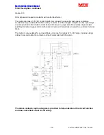
For panel mounted filter applications
interconnection between the filter, its power
source the cappanels and the drive is
shown in Figure 19. Table 10 lists the wire
range and terminal torque requirements as
a function of filter current ratings. Use table
10 for selecting conductors that interconnect
the HMR and capacitor assemblies. Filters
that use multiple cappanels share total cap
current shown on table 3.
Refer to the drive user manual for
instructions on interconnecting the drive and
motor and the correct start-up procedures
for the drive.
The filter is designed for use with copper
conductors with a minimum temperature
rating of 75 degrees C.
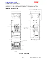
For filters supplied in general purpose
NEMA, 2 & 3R cabinets, interconnection
between the filter, its power source, and the
drive is shown in Figure 20. Refer to Figures
14 to 18 for the location of input, output, and
ground and over temperature switch
terminals. Table 10 lists the wire range and
terminal torque requirements as a function
of filter current ratings. Refer to the drive
user manual for instructions on
interconnecting the drive and motor and the
correct start-up procedures for the drive.
Grounding and Ground Fault Protection
The filter must always be grounded with a
grounding conductor connected to all
ground terminals.
Due to high leakage currents associated
with variable frequency drives, ground fault
protective devices do not necessarily
operate correctly when placed ahead of a
Matrix Filter® feeding a drive. When using
this type of device, its function should be
tested in the actual installation.
Over Temperature Switch
The temperature switch is provided to
annunciate adverse filter heating. Damage
to the filter or drive may be avoided by
interlocking this switch to shutdown the
drive or illuminate a service light; see
figures 19 and 20 for connection diagrams.
Read the vendor drive manual for details in
using interlock inputs.


