This page intentionally left blank
Страница 1: ...AL WARNING High Voltage Only a qualified electrician can carry out the electrical installation of this filter Quick Reference Performance Data Pages 5 10 Selection Guide Pages 11 14 Installation Guide...
Страница 2: ...This page intentionally left blank...
Страница 3: ...OR CURRENT 7 TYPICAL HARMONIC SPECTRUM 8 MATRIX E SERIES LOAD VS POWER FACTOR 8 TYPICAL PERFORMANCE WITH UNBALANCED LINE VOLTAGE 9 ALTITUDE DERATING 9 VOLTAGE DISTORTION DERATING 10 4 HOW TO SELECT 11...
Страница 4: ...Diagram 18 Figure 5 2 Open Panel Interconnection 19 List of Tables Table 3 1 Performance Specifications 5 Table 3 2 Filter Efficiency Watt Loss Capacitor Current 6 Table 3 3 Filter Efficiency Watt Los...
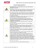
Страница 5: ...lead to serious injury or death WARNING General Warning warns of situations that can result in serious injury or death if proper precautions are not used Caution General Caution identifies situations...
Страница 6: ...erminals Only spare parts obtained from MTE Corporation or an authorized MTE distributor can be used After removing power allow at least five minutes to elapse and verify that the capacitors have disc...
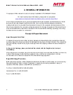
Страница 7: ...tatement Upon Receipt of this Filter The Matrix E Series Harmonic Filter has been subjected to demanding factory tests before shipment Carefully inspect the shipping container for damage that may have...
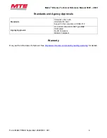
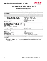
Страница 8: ...nd Agency Approvals Standards CSA C22 2 No 14 95 CE EN50178 1997 Support in the compliance of IEEE 519 Agency Approvals UL and cUL listed to UL508 Type MAE CE Marked RoHS Compliant REACH Compliant War...
Страница 9: ...ad 17 40 load System Power Conditions at Rated Current THVD 2 Line Voltage Unbalance 1 Source Impedance Maximum 6 Minimum 1 5 Maximum output voltage at no load RMS Peak 5 Minimum output voltage at ful...
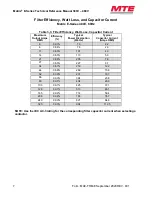
Страница 10: ...ncy Typical Power Dissipation Watts Typical Capacitor Current Amps RMS 6 98 5 65 2 4 8 98 7 74 3 2 11 98 8 94 4 4 14 98 9 106 5 6 21 98 7 192 8 4 27 98 9 212 10 8 34 99 1 205 13 6 44 99 1 270 17 6 52...
Страница 11: ...y Typical Power Dissipation Watts Typical Capacitor Current Amps RMS 6 98 3 70 2 2 8 98 4 79 2 9 11 98 3 101 4 0 14 98 5 113 5 0 21 98 6 205 7 6 27 98 5 227 9 7 34 98 7 219 12 2 44 98 8 289 15 8 52 99...
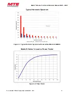
Страница 12: ...Reference Manual 380V 480V Form MAE TRM E September 2020 REV 001 8 Typical Harmonic Spectrum Figure 3 1 Typical Harmonic Spectrum with and without Matrix E SERIES Matrix E Series Load vs Power Factor...
Страница 13: ...Table 3 4 Typical Performance with Unbalanced Line Voltage All Components at Nominal Values and Worse Case Service Conditions 100 Load Nominal THID 11 39 1 Unbalance 11 45 2 Unbalance 11 50 3 Unbalanc...
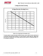
Страница 14: ...a Matrix E Series harmonic filter in environments with a preexisting voltage distortion Example In a system with 10 voltage distortion a Matrix filter will need to be oversized by 5 5 to obtain the sa...
Страница 15: ...e use of information circuits or equipment described in this instruction manual Matrix E Series harmonic filters are available in Open Panel configurations For inverters feeding isolation transformers...
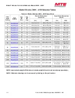
Страница 16: ...AE TRM E September 2020 REV 001 12 Model Number Code System MAE P _ _ _ _ x Matrix E Series Enclosure Type P Panel Mount No Enclosure Current Rating 0006 is 6 Amps 0083 is 83 Amps 0320 is 320 Amps Vol...
Страница 17: ...44 MAEP0044C 43 20 12 0 x 7 1 x 6 1 305 x 180 x 155 10 6 x 4 6 269 x 117 52 MAEP0052C 55 25 14 5 x 9 6 x 6 9 368 x 244 x 175 9 1 x 4 6 7 5 x 3 9 231 x 117 191 x 99 66 MAEP0066C 60 27 14 6 x 9 6 x 6 7...
Страница 18: ...305 x 180 x 155 7 5 x 3 0 9 1 x 4 6 191 x 76 231 x 117 52 MAEP0052D 53 24 14 5 x 9 6 x 6 9 368 x 244 x 175 9 1 x 4 6 231 x 117 66 MAEP0066D 56 25 14 6 x 9 6 x 6 7 371 x 244 x 170 7 5 x 3 0 10 6 x 4 6...
Страница 19: ...etween the reactor and capacitor is required by the customer Open panel Matrix E Series filters are designed for mounting within the customer s enclosure When determining the internal temperature rise...
Страница 20: ...he drive to prevent filter damage due to abnormal operating conditions The temperature switch is normally closed and will open when an internal reactor temperature of 180 C is reached See Table 5 1 Ov...
Страница 21: ...minimum temperature rating of 75 degrees C Wiring Checks Using Figure 5 1 Basic Schematic Diagram p18 visually check the wired components to confirm verify and correct wiring Then with a multi meter...
Страница 22: ...Matrix E Series Technical Reference Manual 380V 480V Form MAE TRM E September 2020 REV 001 18 Matrix E Series Schematic Diagram Figure 5 1 Basic Schematic Diagram...
Страница 23: ...ries Technical Reference Manual 380V 480V 19 Form MAE TRM E September 2020 REV 001 Matrix E Series Interconnection Diagram Figure 5 2 Open Panel Interconnection MATRIX E Series OPEN PANEL INTERCONNECT...
Страница 24: ...14 23 21 14 6 16 16 CAP 344TP 14 23 27 14 6 16 16 CAP 345TP 14 23 34 14 6 16 16 CAP 346TP 12 23 44 14 6 16 16 CAP 347TP 12 23 52 Flat copper tab N A 16 CAP 346TP CAP 342TP 10 23 66 Flat copper tab N...
Страница 25: ...TP 14 23 27 14 6 16 16 CAP 343TP 14 23 34 14 6 16 16 CAP 349TP CAP 343TP 12 23 44 14 6 16 16 CAP 339TP CAP345TP 12 23 52 Flat copper tab N A 16 CAP 346TP 10 23 66 Flat copper tab N A 16 CAP 347TP CAP...
Страница 26: ...ng to the utility drive and motor is in accordance with the power wiring connection diagrams shown in installation instructions section 3 Check that moisture has not condensed on the filter components...
Страница 27: ...alified personnel only and in accordance with OSHA Regulations High voltage is used in the operation of this filter Use Extreme caution to avoid contact with high voltage when operating installing or...
Страница 28: ...00K ohms check a Phase to phase U1 V1 W1 U1 mechanically activate contactor if present after reactor and caps charge reading should be about 40K total equivalent breeder resistance value Open circuit...
Страница 29: ...EM Filter output voltage is not within specification Possible cause Filter input voltage is not within specification Solution Check the AC input line voltage and verify that it is within tolerance Ref...