


dV E-Series Technical Reference Manual 208V – 600V
13
Form: DVT-TRM-E December 2021 Rev. 001
4. HOW TO SELECT
Selection Guide
The dV E-Series motor protection filter is intended for use on inverter duty motors. It will
typically be used with lead lengths up to 1,000 feet. The dV E-Series motor protection filter
eliminates reflective wave, provides peak voltage protection, and rise time reduction.
The suitability of this filter for a specific application must therefore be determined by the
customer. In no event, will MTE Corporation assume responsibility or liability for any direct or
consequential damages resulting from the use or application of this filter. Nor will MTE
Corporation assume patent liability with respect to the use of information, circuits or equipment
described in this instruction manual.
NOTE: For non-inverter duty motors, please refer to MTE’s
The dV E-Series motor protection filters are available in Kit, Open Panel, NEMA 1/2, and 3R
mechanical configurations.
Please verify information below for proper selection:
Lead Length
: This product is suitable for applications with motor leads up to 1,000 ft.
Contact MTE Application Engineering for possible longer applications.
Voltage
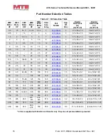
: Input voltage from 208V – 600V. See Table 3-1: Performance Specifications
for specification.
*Current Rating
: Support for 3 Amps – 750 Amps.
Switching Frequency
: Support for carrier frequency of 2kHz – 4kHz.
See Table 3-1:
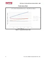
Drive Output Frequency
: Support for 0Hz to 60Hz without derating. See
Figure 3-3: Current Derating for Drive
for derating curve.
Temperature
: Maximum ambient temperature, 60C (open), 50C (enclosed). See
Table 3-1: Performance Specifications
for specification.
Altitude
: 3,300 feet above sea level without derating. See Figure 3-2: Altitude Derating
for derating curve.
Enclosure Type
: NEMA 1/2 & NEMA 3R – see
for enclosure
descriptions.
Motor Insulation Class
: Verify motor meets inverter duty standards per NEMA MG1
Section 31.
* NOTE: dV E-Series filters can be paralleled for higher current ratings. Contact MTE
Application Engineering for more information.
Содержание dV E Series
Страница 2: ...This page intentionally left blank...