2 of 3
Advisory MTD-214
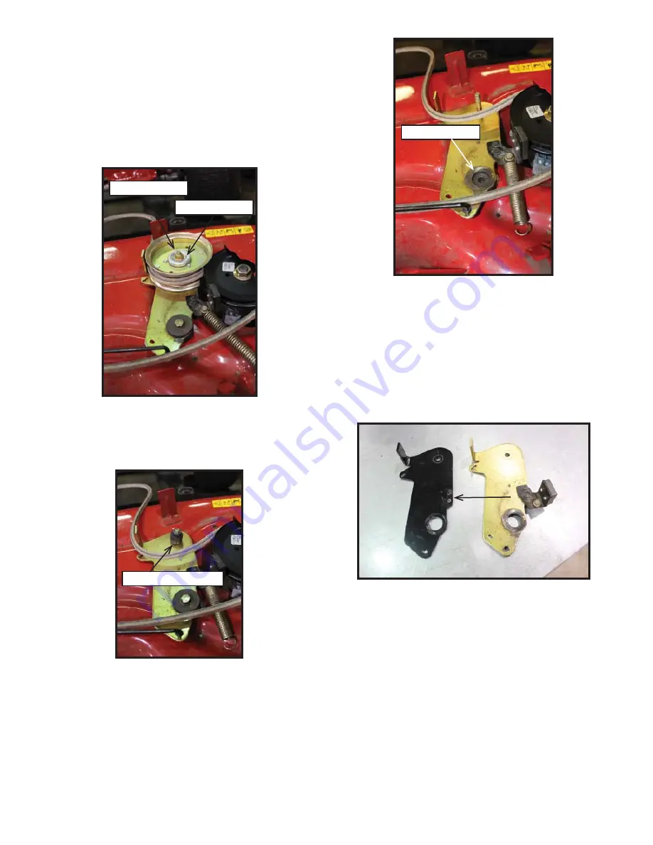
4. Remove the idler pulley and the shoulder spacer. Figure
3. The bolt can be removed later, with the idler bracket.
Figure 3
5. Using a spring puller or other suitable tool, unhook the
brake spring from the anchor point on the mowing deck.
6. Remove the 3/8-16x1.75” hex screw that secures the
idler bracket to the cutting deck. NOTE: The nut can be
accessed from under the cutting deck. Also remove the
pulley spacer. Figure 4.
Figure 2
Pulley Spacer
Figure 4
7. Remove the idler bracket from the mowing deck brake
rod by rotating it 180 degrees on the brake rod, to
release it from the keyhole slot in the idler bracket.
Remove the pulley mounting bolt and brake spring from
the idler bracket.
8. Transfer the brake assembly to the new idler bracket
using the existing self-tapping bolts. Tighten the bolts
securely, being careful not to over tighten them. Figure
5.
Figure 5
3/8-16 Hex Nut
Pulley Cap
Shoulder Spacer
9. Install the new idler bracket onto the mowing deck in re-
verse order of removal using the new locknuts. Tighten
all hardware securely.
10. Install the mowing deck back onto the rider per the
instructions found in the Operator’s Manual
11. Operate the rider in a safe area to verify the correct op-
eration of the mowing deck and that all safety features
are functioning correctly.
Installation Procedure:
1. Remove the mowing deck per the instructions found in
the Operator’s Manual.
2. Place the deck on a suitable deck cart or workbench
that allows access to work underneath of it.
3. Remove the 3/8-16 hex flange nylon locknut and pulley
cap from the idler pulley. Figure 2.
NOTE: The bolt
head can be accessed from below the idler bracket.


