MSR mGard 2 MC2 Series Скачать руководство пользователя страница 5

User Manual - PolyGard

®

2 / µGard

®

Sensors for Toxic Gases and Oxygen


Page  

5


PolyGard

 / µGard

® 

are registered trademarks of MSR 


GA_SC2_MC2_Tox_D_0618 

 
Phone 0049(0)8531/9004-0 

Fax: 0049(0)8531/9004-54 


      Specification subject to change without notice 

MSR-Electronic GmbH, Würdinger Str. 27, D 94060 Pocking       www:msr-electronic.de 


     Printed in Germany 

3  Electrical Connection 

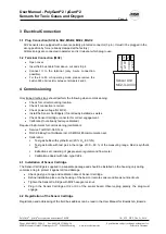
3.1  Plug Connection (SC2) in SB2, MSB2, MSC2, MGC2 

SC2 sensors are equipped with a reverse polarity protected connector (3-

pin). It mustn’t be plugged in the 

wrong position by force (already clamped at the factory). 
All black plugs are connected in parallel, so it is irrelevant which plug to use. 

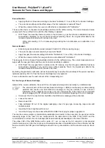
3.2  Terminal Connection (MC2) 


Open cover. 


Insert field bus cable from above, cut and strip it. 


Connect  it  to  the  terminal  (only  3-wire  connection 
possible). 


For  the  4  to  20  mA  operating  mode,  please  remove  the 
built-in 500 ohm resistor between terminals 2 and 3.


4  Commissioning 

Only trained technicians should perform the following when commissioning:  


Check for correct mounting location. 


Check if connection is correct. 


Check power voltage (for MC2). 


Install the Sensor Cartridge(s) if not already installed ex works.  


Check Sensor Cartridge connector for correct engagement. 


Calibrate (if not already factory-calibrated). 

Required instruments for commissioning (calibration): 


Service Tool DGC-06 STL or  


DGC-06 EasyConf Software incl. USB/RS-485 communication set: 
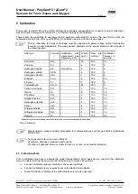
 

Calibration: 


Test gas bottle with synthetic air (20 % O

2

, 80 % N)  


Test gas bottle with test gas in the range of 30 

– 90 % of the measuring range. Rest is synthetic 

air.  


Extraction set consisting of gas pressure regulator and flow meter  


Calibration adapter with tube, type C2Z4. 

4.1  Installation of Sensor Cartridge 

The Sensor Cartridge is supplied in a separate package and should be installed on the housing only during 
commissioning to protect it against dirt and damage.  


Check gas type, range and calibration date of Sensor Cartridge.  


Define installation place on the housing of the basic or remote sensor and break out knockouts.  


Tighten the Sensor Cartridge with M32 hexagon lock nut.  


Plug  in  the  Sensor  Cartridge  at  X2  or  X3  of  the  sensor  board.  Observe  plug  polarity,  the  plug  must 
engage. 

4.2  Registration of the Sensor Cartridge 

Registration and addressing of the field bus address can be read in the User Manual for Boards GA_Boards. 


0

 V

D

C

Sensor Unit
MC2-X-XXXX

1

2

3

+

2

4

 V

4

-2

0

m

A

 /

 2

-1

0

V

o

o

o

Содержание mGard 2 MC2 Series

Страница 1: ...9004 0 Fax 0049 0 8531 9004 54 Specification subject to change without notice MSR Electronic GmbH Würdinger Str 27 D 94060 Pocking www msr electronic de Printed in Germany PolyGard 2 µGard 2 Sensors Sensor Cartridge for Toxic Gases and Oxygen Series SC2 and MC2 Series User Manual June 2018 ...

Страница 2: ...2 in SB2 MSB2 MSC2 MGC2 5 3 2 Terminal Connection MC2 5 4 Commissioning 5 4 1 Installation of Sensor Cartridge 5 4 2 Registration of the Sensor Cartridge 5 5 Calibration 6 5 1 Calibration Work 6 5 2 Exchange of Sensor Cartridge 7 6 Inspection and Service 8 6 1 Inspection 8 6 2 Service and Calibration 8 7 Troubleshooting 9 7 1 Indicators at the SC2 9 7 2 Indicators at the MC2 9 7 3 Basic Sensor Boa...

Страница 3: ...e description of the SB2 MSC2 and MSB2 devices 1 3 Special Mode See description of the SB2 MSC2 and MSB2 devices 1 4 Sensor Element for Toxic Gases and Oxygen The sensor element is a sealed electro chemical cell with three electrodes sensing reference and counter or with two electrodes sensing and reference The ambient air to be monitored diffuses through a membrane filter into the liquid electrol...

Страница 4: ...g Ammoniak E1125 0 59 Ceiling 0 3 m Chlor E1193 2 40 Floor 0 2 0 3 m Fluorwasserstoff E1182 0 71 Ceiling Cyanwasserstoff E1183 0 93 Ceiling 0 3 m Chlorwasserstoff E1186 1 25 Floor 0 3 0 8 m Ethylen E1189 0 97 1 5 1 8 m Fluor E1198 1 31 Floor 0 2 0 3 m Formaldehyd E1185 1 09 Floor 0 3 0 8 m Kohlenmonoxid E1110 0 97 1 5 1 8 m Ozon E1190 1 66 Floor 0 3 m Phosphin E1187 1 18 Floor 0 8 m Schwefeldioxid...

Страница 5: ...2 Install the Sensor Cartridge s if not already installed ex works Check Sensor Cartridge connector for correct engagement Calibrate if not already factory calibrated Required instruments for commissioning calibration Service Tool DGC 06 STL or DGC 06 EasyConf Software incl USB RS 485 communication set Calibration Test gas bottle with synthetic air 20 O2 80 N Test gas bottle with test gas in the r...

Страница 6: ...ion interval in months1 Ammonia NH3 18 300 12 Chlorine Cl2 6 150 6 Hydrogen fluoride HF NO2 80 6 150 6 Hydrogen cyanide HCN 6 300 6 Hydrogen chloride HCL 1 150 6 Ethylene C2H4 6 150 12 Fluorine F2 6 300 6 Formaldehyde CH2O 24 300 6 Carbon monoxide CO 1 150 12 Ozone O3 6 150 12 Phosphine PH3 6 150 12 Sulphur dioxide SO2 6 300 12 Hydrogen sulphide H2S 6 150 12 Silane SiH4 6 150 12 Nitrogen dioxide N...

Страница 7: ...hen the gain calibration has been successfully completed If you exit the menu without pressing Save the original gain data for the measured value calculation will continue to be used By limiting the gain factor calibration will not be possible any more when the sensitivity of the sensor reaches a residual sensitivity of 40 Then the Sensor Cartridge has to be replaced For more information see the u...

Страница 8: ...als depend on the sensor element and can be read from the table Calibration If there are different intervals always observe the shortest one Inspections and services must be documented The date for the next maintenance has to be affixed to the sensor 6 1 Inspection Gas sensors should be controlled regularly by a competent person according to EN 45544 4 The following has to be checked in particular...

Страница 9: ...ed Measure tension at X4 16 28 V DC Pin 1 and 2 Polarity not correct at X4 Connect correctly Connector X4 not plugged in Check the plug Wire breakage Check the wiring Green LED doesn t flash BSB no address Check BSB address address correctly BSB no field bus communication Check field bus wiring topology and termination No measured value at the Tool or Controller SC not or wrongly plugged in Check ...

Страница 10: ... Power consumption for 24 VDC MC2 for toxic gases and oxygen 23 mA max 0 6 VA for 24 V Analog output signal Proportional overload and short circuit proof load 500 Ohm for current signal 50 kOhm for voltage signal 4 20 mA or 2 10 V measuring range 3 2 4 mA or 1 6 2 V underrange 20 21 2 mA or 10 10 6 V overrange 2 mA or 1 V fault 21 8 mA or 10 9 V fault High General Sensor element Electrochemical Pr...

Страница 11: ... bus 1 wire 19200 Baud General Sensor element Electrochemical Pressure range Atmospheric 20 Storage temperature range 5 C to 30 C 41 F to 86 F Storage time 6 months Physical Housing type P Polycarbonate Flammability UL 94 V2 Enclosure colour RAL 7032 light grey Dimensions Housing type P d x H 24 x 22 mm 0 94 x 0 87 in Weight ca 30 g 0 066 lb Protection class IP 65 Mounting Screw type mounting Wire...

Страница 12: ... 10 0 5 0 01 2 60 0 2 1 2 10 45 15 90 36 1 09 Floor 6 E1110 BX 0 100 3 0 5 5 10 4 0 4 0 4 15 50 10 95 72 0 97 1 5 1 8 12 E1110 CX 0 150 2 0 5 5 10 4 0 4 0 4 15 50 10 95 72 0 97 1 5 1 8 12 E1110 EX 0 250 2 0 5 5 10 4 0 4 0 4 15 50 10 95 72 0 97 1 5 1 8 12 E1110 FX 0 300 2 0 5 5 10 4 0 4 0 4 15 50 10 95 72 0 97 1 5 1 8 12 E1110 HX 0 500 2 0 5 5 10 4 0 4 0 4 15 50 10 95 72 0 97 1 5 1 8 12 E1190 AX 0 ...

Страница 13: ... 10 0 100 0 100 0 200 0 5000 0 10 12 10 30 20 0 20 0 1000 150 E1193 XX 2 300 0 5 0 20 20 35 0 300 0 E1182 AX E1183 CX 100 0 100 2 20 38 15 25 5 12 35 0 100 2 E1186 DX 20 0 1000 0 100 0 20 31 20 6 25 0 0 E1189 CX 60 E1198 AX 1000 0 1 1 4 100 0 5000 0 20 0 2 1 2 10 8 1000 0 E1185 BX 10 18 1 3 E1110 XX 2 2 0 2000 5 5000 0 50 0 5 25 0 50 1 50 8 100 20 E1190 XX 2 5 45 4 100 0 300 0 5 0 20 10 35 0 300 0...

Страница 14: ... 0 8531 9004 54 Specification subject to change without notice MSR Electronic GmbH Würdinger Str 27 D 94060 Pocking www msr electronic de Printed in Germany 10 Figures v Fig 1 Fig 3 Basis Sensor Board with Sensor Cartridge SC2 connection to Basic Sensor Board Fig 2 Calibration adapter C2Z4 X2 X3 X7 X4 94 mm 79 mm Mounting Mounting Mounting Mounting 115 mm 130 mm 180 mm D 4 mm ...

Страница 15: ...µGard 2 devices are installed in compliance with all national and local codes and OSHA requirements Installation should be implemented only by technicians familiar with proper installation techniques and with codes standards and proper safety procedures for control installations and the latest edition of the National Electrical Code ANSI NFPA70 The equipotential bonding required also e g secondary...

Отзывы: