


40
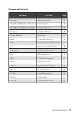
Overview of Components
BIOS_SW1: Multi-BIOS Switch
This motherboard has two built-in BIOS ROMs (Labeled A and B, default BIOS ROM is
A). If one is crashed, you can shift to the other for booting by sliding the switch.
Recovering BIOS
When BIOS updating fails or causes the computer non-bootable, you can recover the
failed BIOS by the steps below. Before recovering, please download the latest BIOS file
that matches your motherboard model from MSI website. And then save the BIOS file
to the root of the USB flash drive.
1.
Power off the computer.
2.
Switch to the normal BIOS ROM with
Multi-BIOS switch
.
3.
Insert the USB flash drive into the computer.
4.
Power on the computer and press Del key to enter BIOS setup during POST.
5.
Select the
M-FLASH
tab and click on
Yes
to reboot the system and enter the flash
mode.
6.
Select a BIOS file to perform the BIOS recovering process.
7.
Switch to the failed BIOS ROM with
Multi-BIOS switch
, and click on
Yes
to start
recovering BIOS.
8.
After the recovering process is completed, the system will reboot automatically.
Important
y
Do not use the Multi-BIOS switch when system is booting up.
y
You can also use the
LIVE UPDATE
utility to flash BIOS. Please refer to BIOS section
for details.
BIOS B
BIOS A
(default)
BIOS B LED
BIOS A LED
Содержание X299M-A PRO
Страница 4: ...4 Quick Start Installing a Processor 1 2 3 6 4 5 7 8 9 10 11 12 13 https youtu be ecdkLMmkya4...
Страница 7: ...7 Quick Start BAT1 Installing the Motherboard 1 2...
Страница 8: ...8 Quick Start Installing SATA Drives http youtu be RZsMpqxythc 1 2 3 4 5...
Страница 9: ...9 Quick Start Installing a Graphics Card 1 http youtu be mG0GZpr9w_A 2 3 4 5 6...
Страница 10: ...10 Quick Start Connecting Peripheral Devices AC version only...
Страница 11: ...11 Quick Start Connecting the Power Connectors http youtu be gkDYyR_83I4 ATX_PWR1 PCIE_PWR1 CPU_PWR1...
Страница 12: ...12 Quick Start Power On 1 4 2 3...