


English
22
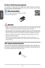
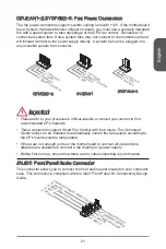
JFP, JFP2: System Panel Connectors
These connectors connect to the front panel switches and LEDs. The JFP
connector is compliant with the Intel
®
Front Panel I/O Connectivity Design Guide.
When installing the front panel connectors, please use the optional M-Connector to
simplify installation. Plug all the wires from the computer case into the M-Connector
and then plug the M-Connector into the motherboard.
Video Demonstration
Watch the video to learn how to Install front panel connectors.
http://youtu.be/DPELIdVNZUI
3.Sp
eake
r
4.VC
C5
1.Sp
eake
r
2.VC
C5
1.+
3.-
10.N
o Pin
5.-
Rese
t Sw
itch
HDD
LED
Pow
er Sw
itch
Pow
er LE
D
7.+
9.Re
serve
d
8.-
6.+
4.-
2.+
JFP
JFP2
Important
On the connectors coming from the case, pins marked by small triangles are
positive wires. Please use the diagrams above and the writing on the optional M-
Connectors to determine correct connector orientation and placement.
The majority of the computer case’s front panel connectors will primarily be
plugged into JFP.
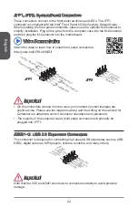
JUSB~2: USB 2.0 Expansion Connectors
This connector is designed for connecting high-speed USB peripherals such as USB
HDDs, digital cameras, MP3 players, printers, modems, and many others.
1.VC
C
3.US
B0-
10.N
C
5.US
B0+
7.Gro
und
9.No
Pin
8.Gro
und
6.US
B1+
4.US
B1-
2.VC
C
Important
Note that the VCC and GND pins must be connected correctly to avoid possible
damage.
•
•
Содержание B85-IE35 Series
Страница 100: ...Deutsch 100 ...
Страница 124: ...Русский 124 ...
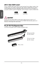
Страница 139: ...简体中文 139 PCI1 3 PCI 扩展插槽 此 PCIe 插槽支持PCIe 界面扩展卡 PCI 插槽 注意 当添加或移除扩展卡时 请首先关闭电源并且从电源插座中拔下电源线 查看关于扩 展卡的文档以便检查必要附件的硬件和软件变化 ...


