Master Relay
-
User’s Manual
5
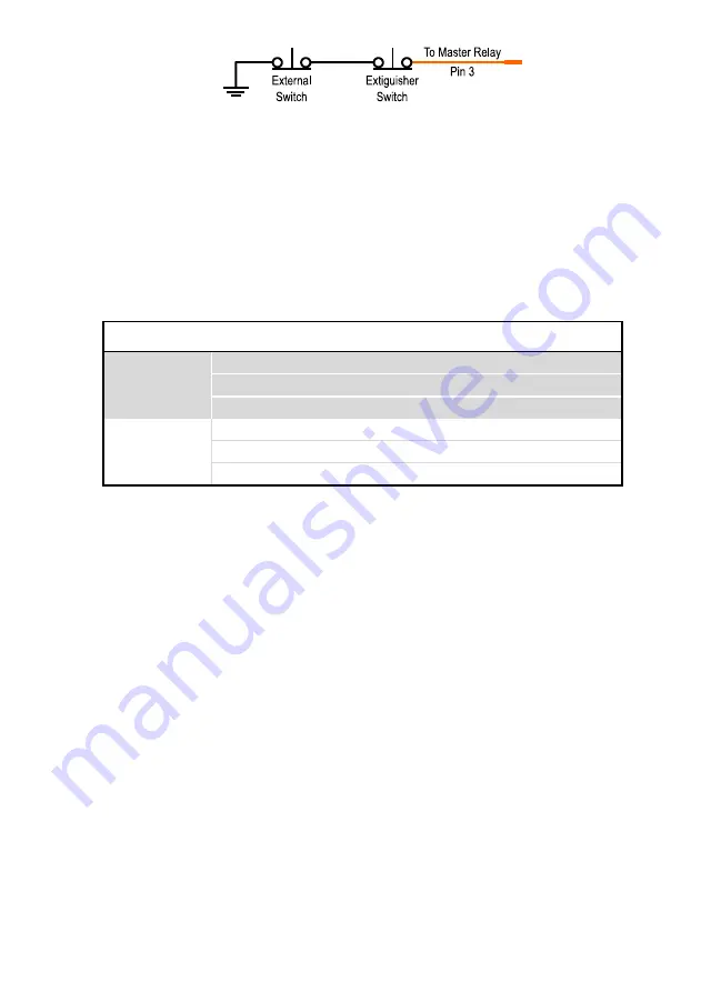
Figure 3: Example multiple external switch configuration
PDM / ECU Connection
Pin 4 of the Master Relay connector provides a logical output for a PDM / ECU allowing engine
shutdown functionality in accordance with FIA rules. The drive of this output can be configured
in the combinations shown in Table 2 below. The device ships standard with configuration 0
(active high, half bridge). In this configuration when the Master Relay
is in an ‘On’ or ‘Normal’
state the output is connected to the battery supply, and when ‘Off’ the output is connected to
ground.
Table 2: PDM output drive configurations
Active State Output Drive Config. Output 'On' Output 'Off'
High
Half Bridge
0
V
battery
GND
Low Side
2
-
GND
High Side
1
V
battery
-
Low
Half Bridge
4
GND
V
battery
Low Side
6
GND
-
High Side
5
-
V
battery
In order to change the output drive to one of the other configurations please refer
the PDM Output Drive Configuration, or specify your requirements when purchasing.
The PDM / ECU output is short circuit protected and current limited to 200mA. To drive larger
loads an external relay is recommended.
CAN Bus Connection
To receive status and channel information from the Master Relay it must be connected to a
compatible device on the same CAN bus. Examples of these include a data logger, dash
display, or ECU. The Master Relay transmits two messages on a configurable address and is
compatible with most CAN capable data loggers on the market. For further information on the
format and transmission refer to the
section.
The Master Relay does not have any internal termination resistors and therefore requires
100R termination resistors at each end of the CAN bus.


