Version 0.1
22
Batteryless telephone system with public address mode BLTS-1006
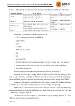
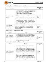
Table 3
–
Description of сommutator telephones and telephones LED light indicators
Control element
Description
SC
«Call»
1 Light signaling of incoming call
2 Light signaling of outgoing call
Сommutator telephones and tele-
phones
«Power»
Indication of external power supply
Сommutator telephones and tele-
phones
«Inductor on»
Light indication of inductor operation status
(while rotated)
Сommutator telephones and tele-
phones
«User»
1 Light indication of the selected user line
2 Light indication of calling user line number
Сommutator telephones
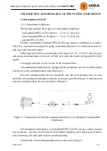
Generally, a сommutator telephone consists of:
‒
USU (with toggle-switches and LEDs);
‒
built-in PSU;
‒
SUIC;
‒
CUESU;
‒
«Inductor on» LED;
‒
CB;
‒
ES;
‒
VC1 and VC2;
‒
SC (provides for mixing and distribution of power voltage and voice signal);
‒
communication device, telephone receiver, headset and intercom helmet;
‒
AP
and EG (inductor).
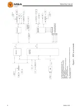
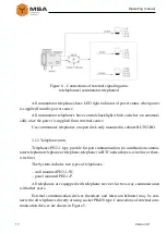
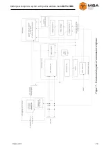
For the functional diagram of сommutator telephone, see Figure 7.
Rotation of EG creates voltage which switches on LIO; then the voltage is sup-
plied to VC1 and VC2, and then
to AP and ES, and to USU as well; at the same time,
generated block signal of external signaling units actuation is then supplied to CUESU.
Once user line toggle is switched on at USU, energy produced by inductor initiates
a call to SUIC, and, at the same time, to user line, actuating call signaling.
Operation of сommutator telephone from external network via built-in PSU fully
repeats operation from inductor (the latter is not used), but energy is supplied to USU and
CUESU only after pressing CB.
Transmission of voice signals to user and back is provided by AP and SC, once
PTT is pressed on the corresponding device.

