Operating Manual
MRW Vib-Control 04
Doc ID: Vib-Control 04-DE
Read the manual prior starting all tasks!
Страница 1: ...Operating Manual MRW Vib Control 04 Doc ID Vib Control 04 DE Read the manual prior starting all tasks...
Страница 2: ...MRW C M Fuisting GmbH Co KG Osterwiesenstr 31 D 73574 Iggingen Brainkofen Tel 49 7175 9207 0 Fax 49 7175 9207 44 E Mail info mrw fuisting com Internet www mrw fuisting com...
Страница 3: ...9 2 4 Foreseeable misuse 9 2 5 Special dangers 10 2 6 Signage 11 3 Technical data 12 3 1 General specifications 12 3 2 Connection ratings 12 3 3 Operating conditions 12 3 4 Serial number 12 3 5 Dimens...
Страница 4: ...5 X17 screw terminal connection in the device 26 5 5 1 Connection variant backup control and external power regulation 27 5 5 2 Connection variant external power regulation via PLC 29 5 6 X18 terminal...
Страница 5: ...ctions In addition the applicable local accident prevention regulations and general safety regulations must be complied with for the machine s implementation The graphic illustrations in this manual a...
Страница 6: ...liability All information and instructions in this operating manual have been provided under due consideration of applicable norms and regulations the current state of technology as well as our many y...
Страница 7: ...to enforce additional claims 1 6 Spare parts WARNING Safety risk if the wrong spare parts are used Incorrect or defective spare parts can cause damage malfunction or total failure they can also impair...
Страница 8: ...f of applicable occupational health and safety regulations and in a hazard analysis identify additional hazards that may exist at the installation site of the control unit due to the special work cond...
Страница 9: ...vibratory drives with a coil current of up to 10 amperes 2 4 Foreseeable misuse Any use that extends beyond the intended use or any other use of the control unit is considered to be misuse and can ca...
Страница 10: ...pply and have the fault repaired Only qualified electricians should perform tasks on the electrical equipment De energise the electrical equipment and ensure that it is de energised for all tasks Befo...
Страница 11: ...led or can become illegible in some other manner Therefore Keep all safety warning and operating instructions that are affixed to the control unit in legible condition Replace damaged signs or sticker...
Страница 12: ...Max power consumption for 0 2 sec 5 A Output current 8 A External power supply 24V DC 0 2 A Fuses slow blow 2 5 A Protection class IP 54 3 3 Operating conditions Specification Value Unit Temperature r...
Страница 13: ...MRW Vib Control 04 27 Oktober 2014 13 v 34 Technical data 3 5 Dimension sheet...
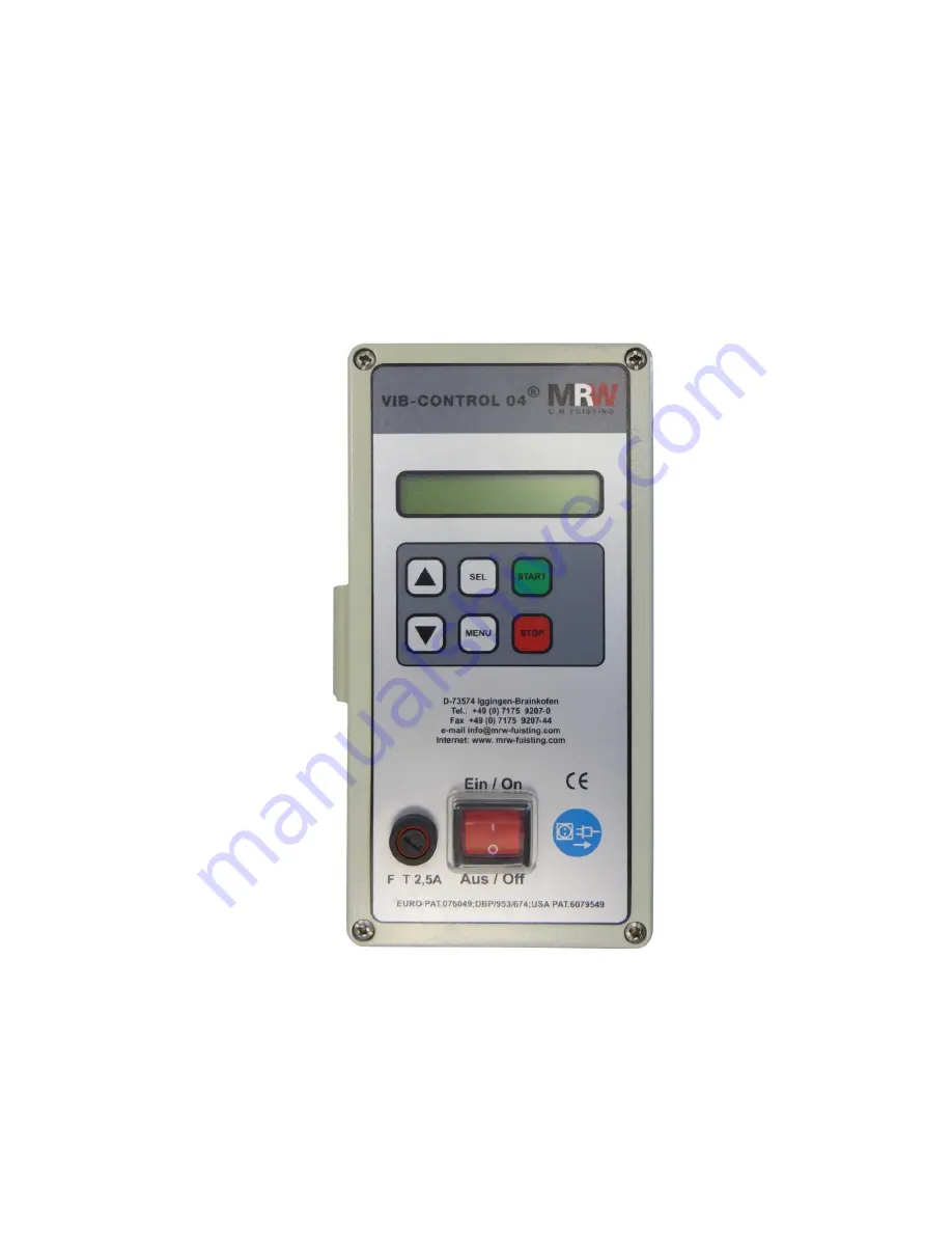
Страница 14: ...eypad membrane keypad 3 2 5A slow blow fuse 4 On off switch 4 1 Operating elements Fig No 4 Button Function Opens the menu Starts the vibratory bowl feeder Stops the vibratory bowl feeder Selects the...
Страница 15: ...Start 147Hz 17Hz Press the Start button to start the frequency search Press the Stop button to stop the frequency search Once the frequency search is successful the status STOP buttons is displayed Se...
Страница 16: ...MIN sensor The input can be inverted The applied voltage at the input is indicated in the display Gentle start Gentle start x xs 0 5s The delay for the gentle start can be set here for between 0 1 an...
Страница 17: ...ottom block can be activated here with Yes and deactivated with No Lock code only when block is activated XXX1 A value between 0 999 can be set as a lock code here The smallest value is 1 All function...
Страница 18: ...ed in this way A prerequisite for a successful frequency search is a fault free vibratory drive clearances coils and springs in perfect condition and a firm connection between the vibratory drive and...
Страница 19: ...ncy is set manually the control type Only speed contr is then is set automatically here Only speed contr If this control type is already set in the menu the control unit then only regulates the speed...
Страница 20: ...ctly connected backup sensor or MAX sensor 4 6 Fault messages in the display Danger Fault messages in the display always indicate an electrical problem The fault must be remedied by a qualified electr...
Страница 21: ...verses the input block After defaulting to factory settings all the parameters to control the vibratory drive and all the inputs and outputs used must be reprogrammed Defaulting To default the MRW Vib...
Страница 22: ...e cylindrical connector for inputs of the PLC or MRW RoboPot System 4 4 pole cylindrical connector for X16 outputs for the downstream control or Vib Control 04 5 Blind plugs for connecting additional...
Страница 23: ...to control the Vib Control 04 with its own potential If using the MRW RoboPot System this connection is prepared and a ready made cable is provided in the accessories 5 3 2 Connection variant 2 Here...
Страница 24: ...is passed on An external potential PLC can be passed on here via a normally open relay For example an additional Vib Control 04 which drives a bowl feeder can be controlled via the normally open relay...
Страница 25: ...ol 04 27 Oktober 2014 25 v 34 Installation and commissioning 5 4 2 Connection variant 2 The 24V potential of the MRW Vib Control 04 is used here to control a relay or an optocoupler which in turn cont...
Страница 26: ...um waiting period of 5 minutes must be observed after disconnecting the control unit from the power and before opening it so that the charge of the capacitators can decrease to a safe level Descriptio...
Страница 27: ...MRW Vib Control 04 27 Oktober 2014 27 v 34 Installation and commissioning 5 5 1 Connection variant backup control and external power regulation...
Страница 28: ...ether the sensor works as normally closed or normally open Input MIN sensor PNP A MIN sensor which controls the filling of a belt section or an accumulation pipe together with a MAX sensor can be conn...
Страница 29: ...y drive can be controlled here via a PLC and an analogue voltage change The lower and upper limits of the performance programmed in the Vib Control 04 menu are adhered to 0V corresponds to the lower l...
Страница 30: ...and L1 are provided for supplying power to the Vib Control 04 Here 110 250 V at 50 or 60 Hz must be provided The power consumption can be 5 A in the short term As a standard a Schuko connector is con...
Страница 31: ...utput Status 08 0000453 00 X4 connecting cable Configured cable for control line for MRW Vib Control 04 X15 to MRW Robo Pot System X4 Length 2m 08 0000044 00 Switch red On Off Mains switch for MRW Vib...
Страница 32: ...MRW Vib Control 04 32 v 34 27 Oktober 2014 Spare parts and accessories Connector 4 pole pin for vibratory drive X 12 080000455 00...
Страница 33: ...ly disconnect it 7 2 Dismantling CAUTION Residual voltage A minimum waiting period of 5 minutes must be observed after disconnecting the control unit from the power and before opening it so that the c...
Страница 34: ...l number Year of manufacture 2014 complies with the provisions of the Low Voltage Directive 2006 95 EC Furthermore the machine complies with all the provisions of the Electromagnetic Compatibility 200...