


Bolt™ Jr+ Quick Start Guide
17
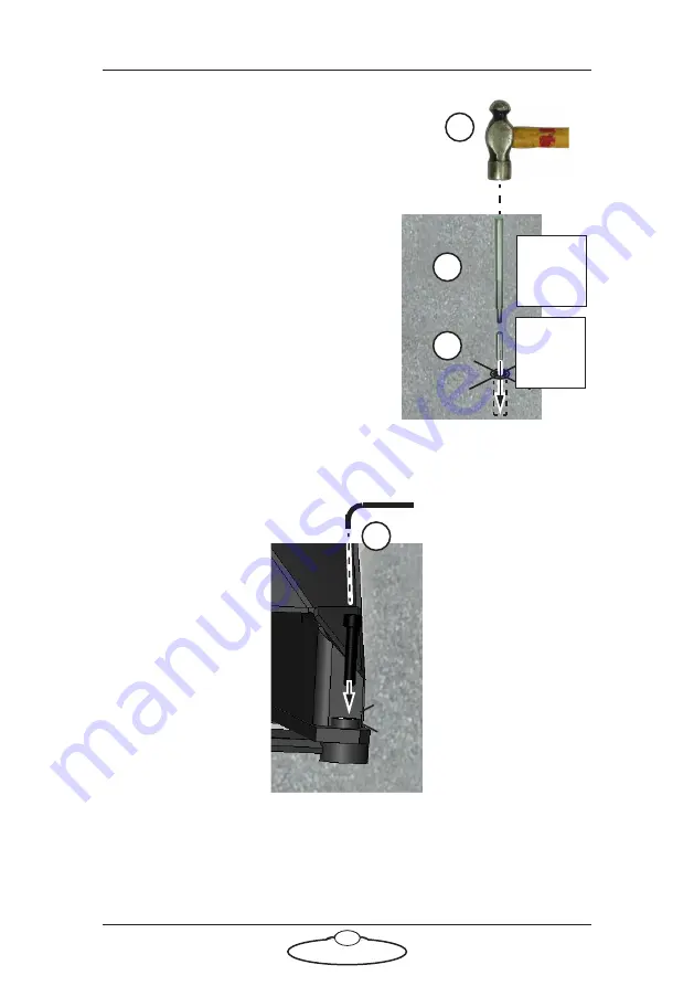
7.
At one of the holes insert the drop-in
anchor insert, threads upward, all
the way to the bottom.
8.
Insert the anchor spreader tool into
the drop-in anchor insert.
9.
Hit the top of the anchor spreader
tool with a hammer until the anchor
is fully spread in the concrete.
10. Remove the anchor spreader tool.
11. Repeat steps 7 to 10 for the other
three corners.
12. Put Bolt Jr+ on Pedestal in place over
the holes.
13. Insert the four retaining bolts
through the corners of the base and
into the drop-in anchor inserts, and
tighten.
Anchor
spreader
tool
Drop-in
anchor
insert
× 4 corners
Содержание CINEBOT Bolt Jr+
Страница 4: ...Bolt Jr Quick Start Guide iv Power Requirements 45...
Страница 17: ...Bolt Jr Quick Start Guide 13 Notes...
Страница 36: ...Bolt Jr Quick Start Guide 32 Notes...
Страница 37: ...Bolt Jr Quick Start Guide 33 Notes...
Страница 45: ...Bolt Jr Quick Start Guide 41 Notes...
Страница 46: ...Bolt Jr Quick Start Guide 42 Notes...
Страница 51: ...Bolt Jr Quick Start Guide 47 Notes...