background image

Installation MRD TNM4000

Release 02 12/2020

Industrial Switch >TNM4000

18

2

Assembly and start-up

The devices have been developed for practical application in a harsh industrial

environment.

On delivery, the device is ready for operation.

The following procedure has been proven to be successful for the assembly of the

device:

Unpacking and checking

Installing the SFP transceivers (optional)

Connecting the power unit connections for supply voltage and alarm relay

contact

Grounding

Installing the device

Startup procedure

Connecting the data lines

2.1

Installing the device

2.1.1

Unpacking and checking

Check whether the package includes all items named in chapter “Scope of

delivery” on page 36.

Check the individual parts for transport damage.

2.1.2

Installing the SFP transceivers (optional)

Figure 4: Fast Ethernet / Gigabit Ethernet Fiberoptic SFP Transceiver

Before attaching an SFP transceiver, first remove the protective cap over the

socket.

Push the SFP transceiver with the lock closed into the socket until you hear it

latch in.

Note:

Only use MRD SFP transceivers (see page 37

Accessories

).

Содержание TNM4000-TP36FF4X16G24P

Страница 1: ...Installation MRD TNM4000 Technical support Release 02 12 2020 http en mrdcom net User Manual Installation Guide Industrial Ethernet Rack mount Switch TNM4000 TP36FF4X16G24P ...

Страница 2: ... embedded software the end user license agreement on the enclosed CD DVD applies The performance features described here are binding only if they have been expressly agreed when the contract was made This document was produced by MRDcom according to the best of the company s knowledge MRDcom reserves the right to change the contents of this document without prior notice MRDcom can give no guarante...

Страница 3: ...1 5 Alarm relay contact 17 2 Assembly and start up 18 2 1 Installing the device 18 2 1 1 Unpacking and checking 18 2 1 2 Installing the SFP transceivers optional 18 2 1 3 Connecting the power unit connections for supply voltage and alarm relay contact 19 2 1 4 Grounding 21 2 1 5 Installing the device 21 2 1 6 Startup procedure 24 2 1 7 Connecting the data lines 25 2 2 Display elements 28 2 3 Basic...

Страница 4: ...s are met The power supply conforms to overvoltage category I or II The voltage supply has an easily accessible disconnecting device e g a switch or a plug The disconnecting device is clearly identified so that in the case of an emergency it is clear which disconnecting device belongs to which line The lines to be connected are voltage free The ground screw on the back of the device is connected t...

Страница 5: ... is damaged switch off the voltage supply and return the device to the plant for inspection Only switch on the device when the housing is closed First connect the ground screw on the back of the device with the protective conductor before you set up the other connections When removing the connections you remove the protective conductor last For supply voltages with protective conductor connections...

Страница 6: ...tically Failure to follow these instructions can result in death serious injury or equipment damage Only technicians authorized by the manufacturer are permitted to open the housing Do not touch the housing during operation or shortly after switching off the device Hot surfaces can cause injury The device must be installed in the horizontal or upright position either in the switch cabinet or on th...

Страница 7: ...Hazardous Locations category Class I Division 2 This device is only suitable for use in explosion hazard areas of category Class I Division 2 Groups A B C D or for use in non explosion hazard areas The maximum operating temperature ambient air is 85 C for general use The maximum operating temperature ambient air is 60 C when the device using 2 5Gbps SFP modules For operation in explosion hazard ar...

Страница 8: ...document Non observance of these safety instructions can cause material damage and or injuries Only appropriately qualified personnel should work on this device or in its vicinity The personnel must be thoroughly familiar with all the warnings and maintenance procedures outlined in this operating manual The proper and safe operation of this device depends on proper handling during transportation p...

Страница 9: ...anges 2011 65 EU RoHS Directive of the European Parliament and of the Council on the restriction of the use of certain hazardous substances in electrical and electronic equipment In accordance with the above named EU directive s the EU conformity declaration will be at the disposal of the relevant authorities at the following address Shanghai MRDcom Co Ltd No 123 Juli Road Pudong Zhangjiang Hi Tec...

Страница 10: ... regulations These requirements are designed to provide sufficient protection against interference when the device is being used in a business environment The device creates and uses high frequencies and can also radiate high frequencies and if it is not installed and used in accordance with this operating manual it can cause radio transmission interference The use of this device in a living area ...

Страница 11: ...plied Installation user manual Reference manual for the graphical user interface Command Line Interface user manual The Industrial NetTime Network Management Software provides you with additional options for smooth configuration and monitoring Simultaneous configuration of multiple devices Graphical user interface with network layout Auto topology discovery Event log Event handling Browser server ...

Страница 12: ... following installation options are available 19 switch cabinet You have the option to choose various media to connect terminal devices and other infrastructure components twisted pair cable multimode F O singlemode F O The ring redundancy concept allows the network to be reconfigured quickly after a failure Product configuration data can be provided by diagnosis displays displaying the operating ...

Страница 13: ...ces all the cable outlet except CLI port MGT port are at the back i e the ports are on the back of the device Rear view of TNM4000 TP36FF4X16G24P Figure 1 Rear panel 1 Grounding screw 2 Power supply unit 3 Alarm relay port 4 LED display elements 5 8 100 1000BaseX SFP Ports 6 8 802 3af at bt PoE PoE PoE 10 100 1000BaseT Ports 7 12 802 3af at PoE PoE 10 100 1000BaseT Ports 8 4 802 3af at PoE PoE 100...

Страница 14: ...espond to a LEDs for displaying the status of the port There are as well as 5 LEDs for displaying the device status The supply voltage connection and the ports are on the back of the device The device allows you to connect a maximum of 36 service ports as well as additional CLI port and MGT port on the front of the device that you can use for diagnosis purposes ...

Страница 15: ...e the following different properties Type of connectable supply voltages DC voltage Level of connectable supply voltages The following tables provide an overview of the possible connections for voltage carrying lines 1 Grounding screw Requiring good ground connection 2 Power supply unit PWR1 PWR2 DC voltage connectable Dual 44 57VDC Power Inputs European terminal 5 pin 3 Alarm relay contact Europe...

Страница 16: ...N access points via 10 100 1000BASE T With PoE these terminal devices are powered by the twisted pair cable TNM4000 TP36FF4X16G24P industrial switches have 8 802 3af at bt PoE PoE PoE 10 100 1000BaseT Ports 12 802 3af at PoE PoE 10 100 1000BaseT Ports 4 802 3af at PoE PoE 100 1000BaseT COMBO Ports The current is supplied on wire pairs transmitting the signal the individual ports are not electrical...

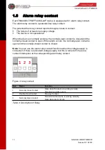
Страница 17: ...nd the normally closed contact is open When alarm occurs the normally open contact is open and the normally closed contact is closed Note You can use the alarm relay contact functions when the voltage supply is connected If there is redundant voltage supply but this is turned off there is a contact interruption at the corresponding alarm relay contact Figure 3 relay contact Item Name Function 1 No...

Страница 18: ...ge and alarm relay contact Grounding Installing the device Startup procedure Connecting the data lines 2 1 Installing the device 2 1 1 Unpacking and checking Check whether the package includes all items named in chapter Scope of delivery on page 36 Check the individual parts for transport damage 2 1 2 Installing the SFP transceivers optional Figure 4 Fast Ethernet Gigabit Ethernet Fiberoptic SFP T...

Страница 19: ...rious injury or equipment damage Note Relevant for North America The torque for tightening the supply voltage terminal block on the device is 4 5 lb in 0 51 Nm Figure 5 Power supply unit dual DC voltage Connection 1 supply voltage 2 relay contact Connection Description pin 1 Plus terminal of the supply voltage pin 2 Minus terminal of the supply voltage pin 3 Protective conductor pin 4 Minus termin...

Страница 20: ...screwdrivers wires etc into the connection terminals for the signal lines and do not touch the terminals Failure to follow these instructions can result in death serious injury or equipment damage Note Relevant for North America The tightening torque for fixing the signal contact terminal block to the device is 4 5 lb in 0 51 Nm For every alarm relay contact to be connected make sure the following...

Страница 21: ...e is grounded via the power supply connections Run the ground connection from the ground screw to the grounding point on the rack or cabinet prior to connecting devices Note The shielding ground of the connectable twisted pairs lines is connected to the rear panel as a conductor Figure 10 Grounding ...

Страница 22: ...access Failure to follow these instructions can result in death serious injury or equipment damage CAUTION OVERHEATING OF THE DEVICE When installing the device ensure that the ventilation slots are not covered Non adherence to these instructions can lead to minor physical injury or material damage Note The shielding ground of the connectable industrial twisted pair lines is connected to the front ...

Страница 23: ...gned to be mounted in a 19 rack Make sure there is sufficient ventilation If necessary provide a fan for the 19 rack This will prevent the basic devices from overheating Measure the depth of the 19 cabinet so that all the lines to be connected can be fed in easily Install the sliding mounting rails in the 19 switch cabinet as instructed by the manufacturer and make sure the device is resting on bo...

Страница 24: ... cabinet Fasten the device by screwing the brackets to the switch cabinet Note When operating the device in environments with strong vibrations the device can be fastened with two additional brackets at the back of the switch cabinet see on page 37 Accessories not included in the delivery 2 1 6 Startup procedure When you connect the supply voltage you start up the device ...

Страница 25: ... mode 100 Mbit s full duplex mode 10 Mbit s half duplex mode 10 Mbit s full duplex mode Delivery state autonegotiation activated The socket housing is electrically connected to the rear panel Pin assignment of the RJ45 socket One line pair pin 3 and pin 6 One line pair pin 1 and pin 2 Remaining pins not used Figure 11 Pin assignment of a TP TX interface in MDI X mode RJ45 socket 10 100 1000 Mbit s...

Страница 26: ...hannels If the inductive coupling has to be reduced the power supply and data cables should cross at a 90 angle You may also choose to use shielded cables Ground the cable shielding at one point in order to avoid causing a ground loop 10 100 Mbit s and 10 100 1000 Mbit s twisted pair connection PoE 10 100 Mbit s and 10 100 1000 Mbit s ports RJ45 sockets enable the connection of terminal devices or...

Страница 27: ... network segments in compliance with the IEEE 802 3 1000BASE X 100BASE X standards These ports support Autonegotiation State on delivery autonegotiation activated 1000 2500Mbit s F O connection 1 1000 2500 Mbit s F O ports SFP slot enable the connection of terminal devices or independent network segments in compliance with the IEEE 802 3 2500BASE X 1000BASE X standards These ports support Autonego...

Страница 28: ...atus display elements Device state These LEDs provide information about conditions which affect the operation of the whole device The following table applies to all device variants LED Display Activity Meaning PWR Power supply Lights up The supply voltage 1 and or 2 are on None The supply voltage 1 and 2 are too low SYS System status Lights up The device is starting and or is not ready for operati...

Страница 29: ...ed information LED Display Activity Meaning 1 36 Data Link status Lights up The port is active and links Flashing The port s data is being transmitted None The port is inactive or link down POE 9 16 POE 17 32 PoE status Lights up A PoE terminal device is connected and receiving power via PoE None No PoE port available or Power over Ethernet function is disabled Table 6 port status ...

Страница 30: ...t evaluated Optical ports autonegotiation CLI interface external management The CLI interface is an RJ45 socket The CLI interface is a serial interface which allows you to connect the following devices locally An external management station a super Windows terminal or PC with appropriate terminal emulation This enables you to set up a connection to the Command Line Interface CLI and to the system ...

Страница 31: ...ent of the CLI interface and the DB9 connector Note On delivery the terminal cable will be offered to you with the device You will find more configuration command in the CLI Manual on the CD ROM MGT interface The MGT interface is an RJ45 socket used for loading the configuration and the software ...

Страница 32: ...ecifications see Technical data Relays are subject to natural wear This wear depends on the frequency of the switching operations Check the resistance of the closed relay contacts and the switching function depending on the frequency of the switching operations MRDcom is continually working to improve and develop our software You can contact our after sales staff for a new version of the software ...

Страница 33: ...NM4000 Release 02 12 2020 Industrial Switch TNM4000 33 2 5 Disassembling the device To detach the device from the switch cabinet remove the screws from the brackets on the device Figure 16 Mounting in the switch cabinet ...

Страница 34: ... AC Imax 2 A at Umax 250VAC Nominal value for DC Imax 2 A at Umax 30V Connection type 3 pin terminal block Climatic conditions during operation Ambient temperature Standard 40 85 Extended a 40 60 Humidity 5 95 non condensing Air pressure Up to 2000m higher altitudes on request a If you are using 2 5G SFP modules then an operating temperature range from 40 C to 60 C applies for your device see page...

Страница 35: ...l Fibers MRD MGIGA GZX 1000M 80km SM 1550nm Dual Fibers MRD MGIGA GSX 850 1000M 550m SM 850nm Dual Fibers MRD MGIGA GSX 1000M 550m MM 1310nm Dual Fibers MRD MGIGA GLX 13 1000M 20km SM 1310TX 1550RX Single Fiber MRD MGIGA GLX 15 1000M 20km SM 1550TX 1310RX Single Fiber MRD MGIGA GEX 13 1000M 40km SM 1310TX 1550RX Single Fiber MRD MGIGA GEX 15 1000M 40km SM 1550TX 1310RX Single Fiber Table 9 Fiber p...

Страница 36: ...de TP port Length of a twisted pair segment Max 100m cat5e cable with 1000BASE T Table 11 TP port 10BASE T 100BASE TX 1000BASE T Power consumption power output Name Power consumption TNM4000 TP36FF4X16G24P Max 35W Scope of delivery Device Scope of delivery TNM4000 TP36FF4X16G24P TNM4000 TP36FF4X16G24P CD ROM including Installation guide User manual and reference manual ...

Страница 37: ...M MRD MGIGA GEX 1000BaseX SFP Module SM 1310 40KM MRD MGIGA GZX 1000BaseX SFP Module SM 1310 80KM MRD MGIGA GSX 850 1000BaseX SFP Module MM 850 550M MRD MGIGA GSX 1000BaseX SFP Module MM 1310 2KM MRD MGIGA GLX 13 1000BaseX SFP Module SM 1310TX 1550RX 20KM MRD MGIGA GLX 15 1000BaseX SFP Module SM 1550TX 1310RX 20KM MRD MGIGA GEX 13 1000BaseX SFP Module SM 1310TX 1550RX 40KM MRD MGIGA GEX 15 1000Bas...

Страница 38: ...tact any MRDcom dealer in your area or MRDcom directly You will find the addresses of our partners on the Internet at http en mrdcom net Contact our support via the email support mrdcom net Support ranges from the first installation through the standby service to maintenance concepts You can contact us Tel 86 21 58330762 E mail sales mrdcom net ...

Отзывы: