

INSTALLATION
This decoder board completely replaces the PC Board in the Atlas
Trainman GenSet Locomotive. Following the Atlas directions, slowly
remove the body shell from the chassis of the locomotive. Be careful as
the supplied headlight wires are very short and may break off from the
LED’s when you remove the body shell. We recomend using a dab of hot
glue to secure the headlight wires close to the headlight location inside
the long hood of the body shell, to avoid them breaking off. Use a 1” to 2”
thin wire to connect
(“T” connection) the
two black wires from the head-
lights. Tape the joint to avoid short circuit. This thin wire will be connected
to the tab marked “headlight com”. Remove the original board with two
Atlas ditch light boards.
Remove the weight from the rear part of the chassis. Remove two capacitors
hidden under the weight. They will not be used. The speaker supplied with
your decoder fits snugly in place where you removed the two capacitors. We
recomend using a small bead of glue to fully secure the speaker to it’s
location. Before installing the ditch light boards please use tape to completely
wrap both front and rear ditch light board holders/slots to prevent the LEDs
from touching the chassis, and shorting out.
See the picture below.
The ditch light boards are already soldered to the decoder for your
conveniance. Be very careful with these wires as they are very fragile.
The
4 ditch lights are tiny SMD led’s. Do not put force on them during install or
when removing the ditch light boards. You may need to remove some of
the tape from the board to ease the fit. However, you must make sure the
rear board be covered with tape, or insulated from the frame.
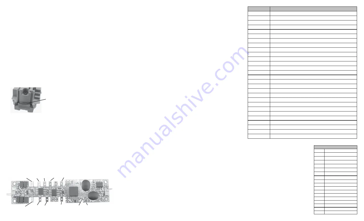
Using the supplied wiring diagram, attach the four pickup, two motor and
three headlight wires to the decoder board and secure using the plastic
clips or by soldering the wires to the tabs on the decoder.
The black
motor wire may need to be extended.
Use all the wire channels in the
chassis to route the wires going to the decoder and use scotch tape in
these locations to keep the wires from moving. If you wish to add a roof
top strobe light to your loco, use the tab marked for strobe light and the
headlight common tab on the decoder.
OPERATION
The decoder has a default address #3. Select address #3 on your DCC system.
Release service brake (F5). You will hear the brake release sound when you
turn off F5. Move up the throttle and the loco should start to move
The decoder
has start up and shut down features. If the loco was previously shut down you
have to start up the engine. Press any function key to start up the engine before
operating the loco. To shut down the engine you must bring the loco to idle and
then press F8 three times. This decoder is default to manual notch setting
(CV122=3).
F9 will notch up and F8 will notch down. If you want automatic
notching enabled set CV 122 = 0. It has three independent diesel genset prime
mover sounds. The second engine will turn on at notch 4 and
turn off below
notch 4. The third will turn on at notch 6 and and turn off below notch 6. This
d
ecoder also mimics the real GenSet, and if left idling for a long period of time
will shut down and restart automatically at specific intervals to conserve fuel.
Shutting off the sound in CV49 will not disable the horn. The decoder has two
types of diesel prime movers. You can use F12 or CV 123 to select the desired
prime mover sound. You can use F19 to select 34 different horn sounds and
use F18 to select 8 different bell sounds. With MRC Prodigy Advance
2
DCC
which has 28 functions, you can easily setup and access all the decoder’s
functions. If not, you may not be able to access all the features of the decoder.
And you have to use the CV program to setup the decoder.
Right
pickup
Right
pickup
Motor
red
Headlight
common
Left pickup
Left pickup
Motor
(black)
Front
light
Rear
light
Strobe light Speaker plug
Function
Idle/Moving
F1
Bell on/off
F2
Horn
F3
Ditch Lights on/off
F4
Coupling 1
F5
Brake release (idle) / brake squeal (moving)
F6
Strobe Light on/off
F7
Air hose firing / uncoupling lever
F8
3 times will shut down when in idle / Manual notch down
F9
Engine cooling fan / Manual notch up
F10
Rail wheel clack (only moving)
F11
Traction air compressor
F12
Change prime mover type, (2 types and off)
F13
Short air release
F14
Coupler crash
F15
Air compressor
F16
Flange squeal
F17
Air release
F18
Change bell type (use F1 to turn off bell after adjustment)
F19
Horn type select (total 22 different horns)
F20
Associated loco sound
F21
Change bell volume (use F1 to turn off bell after adjustment)
F22
Change horn volume
F23
Change prime mover volume
F24
Safety valve pop
F25
Air release
F26
Flange noise
F27
Sand drop
F28
Ditch Lights flash when F3 is activated
Use tape to completely wrap
both front and read ditch light board
holders to prevent LEDs from touching
the chassis
SERVICE BRAKING
To apply service brake (needs CV #4 set to almost maximum) set throttle to zero
and press F5. The loco will slow down fast and you will hear the brake squeal.
You can pump the brake by turning F5 on and off to stop the loco at desired
location. The brake rate is proportional to deceleration rate that you program in
CV4. If you forget to turn off F5 and move the throttle up. The loco will move.
However, when you release the throttle the service brake will apply again. The
service brake can only operate when throttle is at 0. If you don’t hear the brake
sound program CV115 with a value of 2.
BACK EMF LOAD CONTROL (PID CONTROLLER)
This decoder is equipped with adjustable back EMF load control feature. It is a
closed loop speed control. With back EMF load control the locomotive will
maintain its speed regardless of pulling up hill or driving down hill. You may
program the back EMF load control intensity, CV124, to a lower value to get less
back EMF load control. This will enable the locomotive to slow down during uphill
travel like a real locomotive.
The PID controller contains three components: proportional gain (CV113); the
integral gain (CV114); and derivative gain (fixed). Designing (tuning) a PID
controller is a kind of “rocket science”. So we optimized these gains at the
factory but still give the customer final adjustments. We recommend that you do
not change these settings. Too much gain may cause the motor to oscilate
(become unstable). Too little gain may cause a slow response. Additional
knowledge of PID feedback control is required before attempting to adjust CV113
and CV114. If CV113 and CV114 are programmed incorrectly, the locomotive will
not run smoothly. Program CV125 to “1” will automatically restore the default PID
controller settings.
If you can not get the PID controller work properly or
you don’t know to tune it, you should program CV6 to enable adaptive
PID control to let the decoder to select the best back EMF control for
your loco.
You can also turn off the Back EMF load control by program CV124
with a value of 0 if the adaptive control fails.
The decoder has 17 different lights
effects. CV 117 controls both front and
rear headlight effect. Use F0 to turn on
or off the Headlights. If you use 1.5V
bulbs or LED’s, you should connect a
1k ohm resistor in series to one of the
leads to reduce the voltage. You may
need to program brightness CV120 to
adjust the LED light effect for perfect
ditch, gyra and mars light. If you use
Rule17 or dim-bright-off light effect you
may also need to program CV116 to
adjust the brightness of the dim light.
LIGHT EFFECT PROGRAMMING CHART FOR CV#117
Value
Light effect
0
Normal on/off
1
Dynamo effect (fading)
2
Dim, bright, off cycle
3
Rule 17
4
Both headlights on
5
Ditch Light type A
6
Ditch Light type B
7
Gyralite
8
Mars Light
9
Prime strato light
10
Single strobe light
11
Double strobe light
12
Rotating beacon
13
Fred Rear End Flashing
14
Firebox Flicker A
15
Firebox Flicker B
16
Engine Exhaust Flicker
Headlight effect CV117


