

INSTALLATION
For newer locomotives with circuit board and wires, simply remove the old circuit
board and follow the diagram to install the decoder. Hook up the front headlight to
the tabs marked as FL and COM. Hook up the rear headlight to the tabs marked as
RL and COM. For accessory light, hook up to ACC and COM.
For older model locomotives such as Atlas/Kato RS-1, RS-3 and RSD-4,
follow the installation tips.
There are no bulbs furnished with this decoder, as modification to the internal light
bars and internal weights may be needed to complete installation. New lenses and
bulb retainers are to be fabricated by the decoder installer. Use of DCC rated bulbs
is reccomended. The speaker is attached to the decoder with a plug. If you have
enough room inside the locomotive, a larger speaker from MRC can be used in place
of the 18mm round one included.
Remove the body shell of the locomotive by following the directions that came with
it. There is a centrally mounted board mounted on the chassis with one light bulb
mounted to it. Disconnect the four black pick up wires that are attached to the
corners of the board and label them right side and left side. Gently slide the motor
brush pick up tabs from under the brass pick up strips running lengthwise across the
circuit board. Pop the board off the retention clips and discard. Cut the motor brush
pick up tabs slightly short, leaving enough room to solder a short piece of wire to
each tab. These two wires then get soldered to the decoder’s motor terminals, [see
diagram]. Solder the four pick up wires from the trucks to the four corner terminals of
the decoder, keeping left side pick up wires to one side of the board and right side
pick up wires to the other side of the board, [see diagram]. Before attaching the
decoder to the retention clips on top of the motor, place a piece of insulating tape on
top of the motor to isolate the bottom of the decoder to the top of the motor, motor
brush tabs and wires. Decoder orientation does not matter as some locos ran long
hood forward and some ran short hood forward. If the locos direction does not match
your particular road name, you can reverse the decoder orientation, or reverse the
two wires on the motor brush terminals, or program CV # 29 to reverse direction.
There are two light bars running lengthwise inside the body shell. These must be
shortened or removed to accomodate the decoder. Choice of headlight/number
board lighting is left up to the decoder installer. The speaker can be mounted on
the decoder in the space provided if there is enough internal body shell clear-
ance. If not it can be mounted to the underside of one of the hoods. Some of
these locos have weights that sit over the gear towers, these must be trimmed
down to gain clearance when mounting the speaker to the undersides of the
hoods. Remove the paper backing from the face of the speaker to expose the
glue ring and press speaker into the desired location.
If your loco has more space for a large speaker we recommend to order 20mm
or even 28mm speaker for a better sound quality.
If you use 1.5V bulbs or LED’s, you should connect a 2k ohm resistor in series to
one of the leads to limit current.
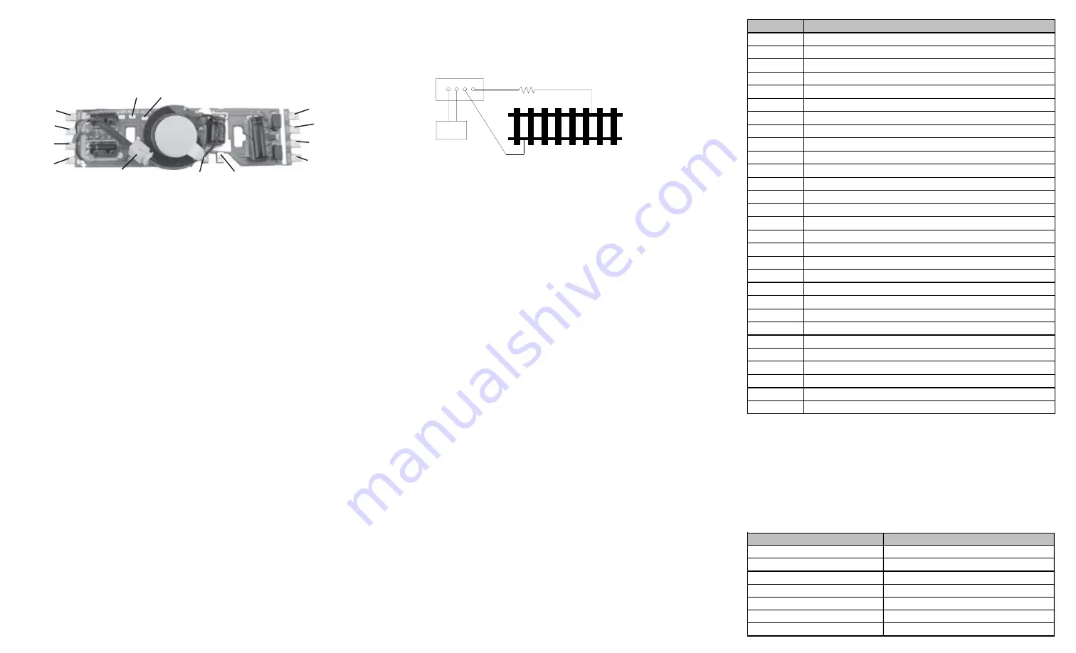
MAKING A TEST TRACK
We strongly recommend building a test track with a 27 ohm resistor to limit
current. Only test your installed decoder on the test track. The test track will
reduce the chance of damaging your decoder due to an incorrectly installed
decoder.
TESTING
The decoder has been programmed to address #3, 28/128 speed steps. To test,
place the loco on the test track. Select address #3 and 28 speed step. Move up
the throttle and the loco should move. Push the light button [F0] and headlight
should come on. Change the direction of the loco and the loco should change
direction. The loco cannot reach full speed, due to the resistor. If all the above
occurs, you passed the test. Congratulations! Do not run the loco for an extended
period of time on the test track or the resistor will overheat. If your installed
decoder does not pass the test, find the problem, correct it and test it again. As long
as you test the decoder on the test track there is little chance of damaging the
decoder. This is why the test track is so important.
OPERATION
The decoder has start up and shut down features. If the loco was previously
shut down you have to start up the engine. Press any function key to start up the
engine before operating the loco. To shut down the engine you must bring the
loco to idle and then press F8 three times.
The decoder has three types of prime mover sound effects. You can use F12 or
CV 123 to select the desired prime mover sound or turn them off. Set CV123 to 0
for Alco, to 1 for SD70 or SD60, to 2 for electric loco, and to 3 for prime mover
sound off. You can use F19 to select 22 different horn sounds and use F18 to
select 8 different bell sounds. With MRC Prodigy Advance
2
DCC which has 28
functions, you can easily setup and access all the decoder’s functions. If not,
you may not be able to access all the features of the decoder. And you have to
use the CV program to setup the decoder.
This decoder allows certain functions to be re-mapped easily, ( CV numbers- 37,
39 and 42). If the values of these CV’s are set to “0” (default), normal DCC
keypad/functions are applicable. Inseting the values shown in the CV chart
allows certain function swapping for example: F3 becomes F4 and vice versa.
BACK EMF LOAD CONTROL (PID CONTROLLER)
This decoder is equipped with adjustable back EMF load control feature. It is a
closed loop speed control. With back EMF load control the locomotive will maintain its
speed regardless of pulling up hill or driving down hill. You may program the back EMF
load control intensity, CV124, to a lower value to get less back EMF load control. This
will enable the locomotive to slow down during uphill travel like real locomotive.
The PID controller contains three components: proportional gain (CV113); the
integral gain (CV114); and derivative gain (fixed). Designing (tuning) a PID
controller is a kind of “rocket science”. So optimized these gains at the factory
but still give the customer final adjustments. We recommend that you do not
change these settings. Too much gain may cause the motor to oscilate (become
unstable). Too little gain may cause slow response. Additional knowledge of PID
feedback control is required before attempting to adjust CV113 and CV114. If
CV113 and CV114 are programmed incorrectly, the locomotive will not run smothly.
Program CV125 to “1” will automatically restore the default PID controller settings.
The decoder default is set to automatic notch. You can program CV122 to 3
for manual notch for realistic operation. And then use F9 to notch up and use
F8 to notch down.
LIGHT EFFECT PROGRAMMING CHART FOR CV#118/119
Both ACC1 and ACC2 has 7 different accessory lights effects. Program CV
#118/119 to choose the desired light effect. CV118 for ACC1 and CV119 for
ACC2. For ditch light both CV118 and CV119 must be 0. In ditch light mode, use F3
to turn on/off and use F28 to enable/disable flash. When you blow the horn the
ditch lights will flash. The ditch lights will remain flashing for several seconds
after horn is off.
CV118/119 value
ACC#1/ACC#2 Light effect
0
Ditch light
1
Gyra light
2
Marslight
3
Prime strato light
4
Single strobe light
5
Double strobe light
6
on/off
Function
Idle/Moving
F0
Lights on/off
F1
Bell on/off
F2
Horn
F3
Mars light on/off with air releas e
F4
Coupling 1
F5
Brake releas e (idle) / brake s queal (m oving)
F6
Dynam ic brake on/off
F7
Air hos e firing/uncoupling lever
F8
3 tim es will s hut down when in idle / Manual notch down
F9
Engine cooling fan / Manual notch up
F10
Rail wheel clack (only m oving)
F11
Traction air com pres s or
F12
Change prim e m over type, (3 types and off)
F13
Short air releas e
F14
Coupler cras h
F15
Air com pres s or
F16
Flange s queal
F17
Air releas e
F18
Change bell type (us e F1 to turn off bell after adjus tm ent)
F19
Horn type s elect (total 22 different horns )
F20
As s ociated loco s ound
F21
Change bell volum e (us e F1 to turn off bell after adjus tm ent)
F22
Change horn volum e
F23
Change prim e m over volum e
F24
Safety valve pop
F25
Air releas e
F26
Flange nois e
F27
Sand drop
F28
Mars light flas h enable/dis able with Air releas e (CV 121)
com
com
pick up
pick up
pick up
pick up
front light
motor
motor
ACC1
ACC2
rear light
speaker connector
Figure 2. Diagram of test track
DCC base unit
Power supply
Test track
27 ohm resistor