

INSTALLATION
It is quite a challenge to install this decoder into an “N” scale diesel locomotive.
You should have some basic electronics knowledge
The body shell, and fuel tank casting must be removed from the chassis, and the
entire frame must be disassembled. Mark the top of the motor with a dab of paint
or permanent marker; remove the original circuit board, motor, driveshafts,
bearings, and trucks.
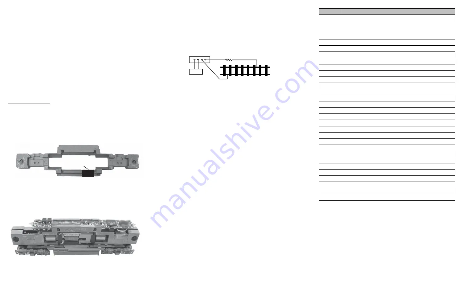
The top portion of each frame half that touches the motor brush tabs
should be insulated with a small piece of clear tape.
The decoder replaces the original circuit board of the locomotive and should fit in
the same location. Assemble one half of the frame first, installing the decoder,
motor, driveshafts, bearings, trucks, and frame spacers. Gently place the other
frame half on top of the completed half, checking clearances and if there is any
binding of the drive mechanism. Correct any trouble spots at this point. Also
check to make sure the motor brush tabs are not touching the frame halves and
the clear tape is correctly positioned at the motor brush tab points to avoid
shorting out the decoder. Now you can install the insulated bolts and nuts to
secure both frame halves together.
Re-check installation!!!
If at this point you are satisfied with the mechanical
installation of the decoder and all associated parts, it is time to check the
installation on a test track. Do not install body shell until testing is done. See
section on “Making a Test Track”, and “Testing”
*Note- This new decoder has the speaker mounted to the underside of
the circuit board. This makes installation easier with no frame milling
required.
Figure 1.
Figure 2. shows how to install 0001812 decoder
MAKING A TEST TRACK
Before you begin decoder installation, we strongly recommend building a test
track with a 27 ohm resistor to limit current. Only test your installed decoder on
the test track. The test track may prevent damage from an incorrectly installed
decoder.
Note: The program track is NOT a test track. The program track does not use a
current limiting resistor. So it can’t protect an incorrectly installed decoder.
TESTING
The decoder has been programmed to address #3, 28/128 speed steps. To test,
place the loco on the test track. Select address #3 and 28 speed step. Move up
the throttle and the loco should move. Push the light button [F0] and headlight
should come on. Change the direction of the loco and the loco should change
direction. The loco cannot reach full speed, due to the resistor. If all the above
occurs, you passed the test. Congratulations! Do not run the loco for an
extended period of time on the test track or the resistor will overheat.
I
f your
installed decoder does not pass the test, find the problem, correct it and test it
again. As long as you test the decoder on the test track there is little chance of
damaging the decoder. This is why the test track is so important.
OPERATION
The decoder has start up and shut down features. If the loco was previously
shut down you have to start up the engine. Press any function key to start up
the engine before operating the loco. To shut down the engine you must bring
the loco to idle and then press F8 three times.
There are four diesel prime mover sounds you may enjoy. You can use F12 to
select either prime mover sound or “off”. You can use F19 to select 34 different
horn sounds and use F18 to select 8 different bell sounds. With MRC Prodigy
Advance
2
DCC which has 28 functions, you can easily setup and access all the
decoder’s functions. If not, you may not be able to access all the features of
the decoder. If you DCC system allows CV programming, you would have to use
this type of programming to access all the features of the decoder.
The decoder default is set to automatic notch. You can program CV122 to 3 for
manual notching for realistic operation. And then use F9 to notch up and use F8
to notch down.
If you don’t have DCC system, you have to use the MRC Blackbox (item
#0001050) for the DC operation. It will allow you to control all of the sounds in
your sound equipped locomotives. The MRC Blackbox is easy to setup and use.
LIGHT EFFECT PROGRAMMING CHART FOR CV#117
Program CV117 to choose 3 different modes of headlight effects (0=normal
directional, 1=off/dim/bright cycle, 2=rule 17).
Bell, Dynamic Brake and Rail Wheel Clack cannot play at the same time. If you
activate the Bell sound [F1], while either the Dynamic Brake or Rail Wheel Clack
sounds are in use, the Bell sound will override the other 2 sounds. Rail Wheel
Clack cannot play while the loco is in idle. When you turn off Dynamic brake and
Rail Wheel Clack sound there will be one second delay.
Function
Idle/Moving
F0
Headlight on/off or rule 17 or cycle of dim, bright, off
Double F0
Double click F0 within 1 second will turn on/off sound (CV49)
F1
Bell on/off
F2
Horn
F3
Air release
F4
Uncoupling lever
F5
Brake release (idle) / brake squeal (moving)
F6
Dynamic brake on/off
F7
Air hose firing/uncoupling lever
F8
Click 3 times during idle will shut down / notch down while CV122=3
F9
Engine cooling fan / notch up while CV122=3
F10
Rail wheel clack (only moving)
F11
Traction air compressor
F12
Select four prime diesel mover types and diesel off
F13
Air release
F14
Coupling
F15
Air pump
F16
Associated loco sound
F17
Flange noise 1
F18
Change bell type (use F1 to turn off bell after adjustment)
F19
Horn type select (total 34 different horns)
F20
Associated loco sound
F21
Change bell volume (use F1 to turn off bell after adjustment)
F22
Change horn volume
F23
Change diesel rumble volume
F24
Air Release
F25
Flange noise 2
F26
Associated loco sound
F27
Sand drop
F28
Air release
Wrap the whole notch with tape to prevent the motor’s contact from touching the
chassis. Otherwise, the decoder will be destroyed if the motor contact touches
any unwrapped part of the chassis.
wrap tape
DCC base unit
Power supply
Test track
27 ohm resistor
Figure 3. Diagram of test track