mr
.
steam
®
Electric Towel Warmers
Installation and Operating Instructions
________________________________________________________________
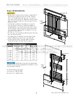
Bracket
Brackets
Insert
Screws
Wiring
Box
Insert
Finished
Surface
of Wall
Marked
Mounting
Location
Header
Washer
Back side of
Towel Warmer
Screw
Electric Drill
Junction Box
Set Screw
Junction
Box Screws
Junction
Box
Junction
Box Cover
Bracket Set Screw
Box Contents
UÊ/ÜiÊ7>ÀiÀÊ
UÊ£®ÊÕVÌÊ ÝÊ-iÌÊ-VÀiÜÊ
UÊ{®Ê À>ViÌÃÊ
UÊ{®Ê À>ViÌÊ-iÌÊ-VÀiÜÃ
UÊ{®Ê>À}iÊ-VÀiÜÃÊ
UÊ/iÀÊ
UÊ{®ÊÃiÀÌÃÊ
UÊ£®ÊiÊiÞ
UÊ£®ÊÕVÌÊ ÝÊÛiÀÊ
UÊ£®ÊÓ»ÊÝÊ{»ÊÕVÌÊ ÝÊ
UÊÓ®ÊÕVÌÊ ÝÊ-VÀiÜÃ
UÊÃÌÀÕVÌÊEÊ"«iÀ>ÌÊ>Õ>
7
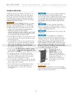
A single gang electric box must be
roughed in. See page 5 for location.
Install Towel Warmers in upright
position only. Locate with pilot light on bottom as
shown. Failure to install properly may result in a
hazardous condition.
IMPORTANT:
DO NOT LOOSEN
SCREWS ON TOP
OR BOTTOM.
LOOSENING SCREWS
WILL CAUSE INTERNAL
LIQUID TO ESCAPE
AND CAUSE
PRODUCT DAMAGE.
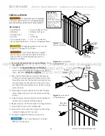
Figure 1:
Towel
Warmer Assembly
Figure 2:
Secure bracket
to finished wall
Figure 3:
Install inserts
to Towel Warmer
Drawings for illustrative purposes only
1. Ensure header and junction box are installed as shown
on page 5 & 6.
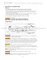
2. Using the allen key provided, loosen the wiring
box set screw and rotate the wiring box into position
shown. DO NOT remove the wiring box.
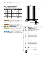
3. Measure the Towel Warmer and mark the locations
on the finished wall, where the brackets and junction
box will be mounted. The bracket mounting locations
should be based on the location of the junction box
(see Table 3 Mounting Dimensions). Verify mounting
points are level.
4. Insert large screw and washer into bracket. Properly
center large screw point onto the marked mounting
location.
5. Using the large screw provided secure the bracket to
the wall with an electric drill (see figure 2).
6. Repeat step 4 and 5 for all bracket mounting locations.
7. Thread the (4) inserts into Towel Warmer.
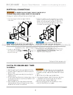
8. Slide junction box cover onto wiring box with wiring
running through junction box cover.
9. Proceed to page 8 for Electrical Connections.
All four mounting points on Towel
Warmer must be used.
INSTALLATION
TO PREVENT SHOCK HAZARD,
TURN OFF ELECTRICITY AT THE MAIN PANEL
BEFORE WIRING. VERIFY WITH MULTIMETER.
REFER
1. Ensu
1. Ens
on
on
TO
re head
re head
age 5 &
ge 5
INSTALLATION,
r and junction box are installed as
r and junction box are installed as
6.
6
OPERATION
to finished wall
hown
AND
CE
MAINTENANC
arked
MANUAL
n key provided, loose
n key provided, loo
PROV
VIDED
n the wiring
n the wiring
WITH
B
PRODUCT
cket
UCT
ODUC
FOR
emove the
emove the
COMPLETE
g
p
g
wiring box.
wiring box.
TIONS
T
INSTRUCTIO
Wa he
T
CT
TIO


