- 5 -
Installing/Removing ICS Switch Modules
IM-G7000A Series modules are designed for installation in ICS switches.
Before inserting the module into the slot, first remove the metal cover
plate. Push the module along the track and firmly connect the module
with the connector. Finally, secure the module by firmly tightening the
screws.
IM-G7000A Series modules are hot-swappable. Take the following steps
to remove modules from the switch:
1.
Push the HOT SWAP button on the module.
2.
Wait for the HOT SWAP STATE LED to turn off.
3.
Loosen the screw(s) and remove the module.
Wiring the Relay Contact
Each ICS switch has one relay output.
FAULT: The relay contact of the 4-pin terminal block connector is used to
detect user-configured events. The two wires attached to the fault
contacts form an open circuit when a user-configured event is triggered.
If a user-configured event does not occur, the fault circuit remains closed.
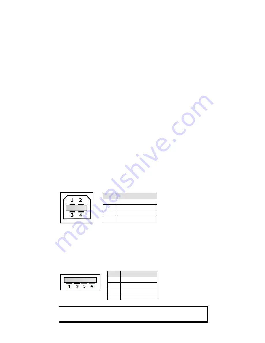
USB Console Connection
The ICS has one USB console port (type B connector) located on the top
panel. Use the USB cable (provided in the product package) to connect
the ICS’s console port to your PC’s USB port, and install the USB driver
(available on the software CD) on the PC. You may then use a console
terminal program, such as Moxa PComm Terminal Emulator, to access the
ICS’s console configuration utility.
USB Console Port (Type B Connector) Pinouts
Pin
Description
1
D– (Data -)
2
VCC (+5V)
3
D+ (Data+)
4
GND (Ground)
USB Storage Connection
The ICS has one USB storage port (type A connector) on the front panel.
Use Moxa’s ABC-02-USB automatic backup configurator to connect the
ICS’s USB storage port for configuration backup, firmware upgrade, or
system log file backup.
USB Storage Port (Type A Connector) Pinouts
Pin
Description
1
VCC (+5V)
2
D– (Data -)
3
D+ (Data+)
4
GND (Ground)
NOTE DO NOT remove the ABC-02-USB USB Automatic Backup
Configurator while writing or reading data.


