– 4 –
– 5 –
– 6 –
www.moxa.com/support
The Americas: +1-714-528-6777 (toll-free: 1-888-669-2872)
Europe: +49-89-3 70 03 99-0
Asia-Pacific: +886-2-8919-1230
China: +86-21-5258-9955 (toll-free: 800-820-5036)
2013 Moxa Inc. All rights reserved.
4.
Connecting the Interfaces
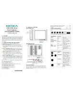
EXPC-1319 peripheral interfaces are located on the bottom panel.
All hardware interfaces ship with protective caps and tethers. To
connect the interfaces, remove the protective caps and tethers.
The screws on the end of the tails also need to be removed. To
protect against water damage, when the connectors are not in use,
please make sure the protective caps have been securely fastened.
Connecting to a Display
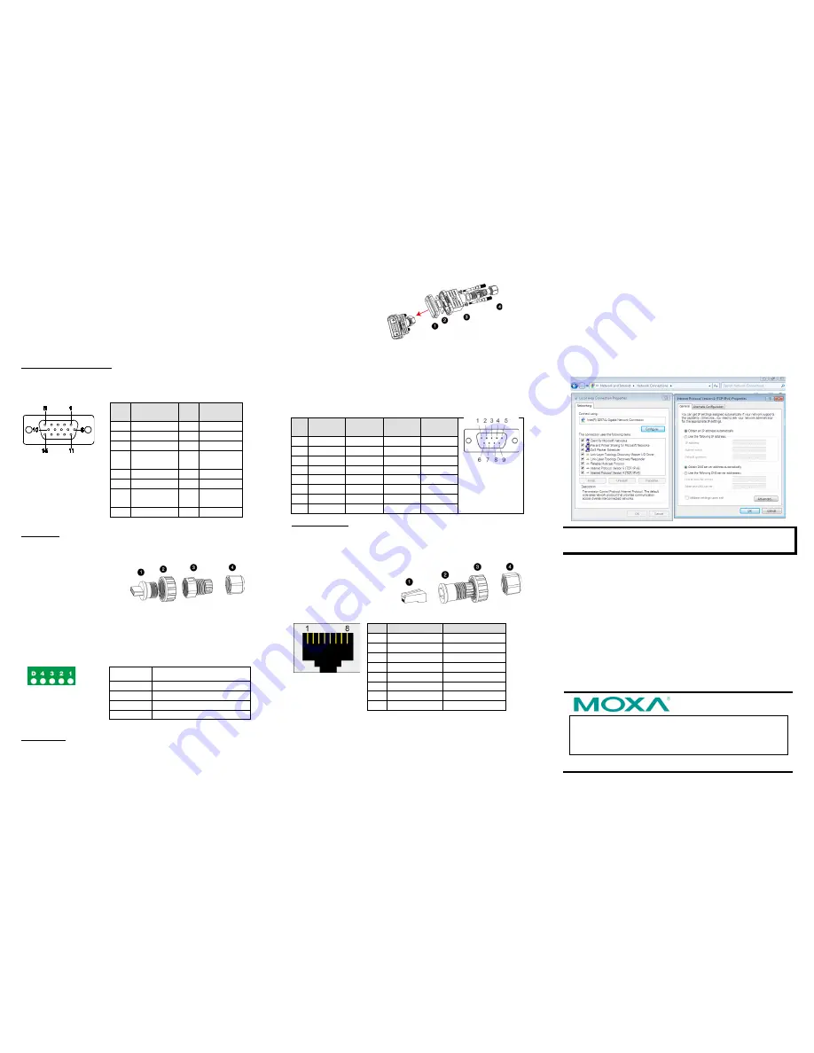
Your EXPC-1319 embedded computer comes with a 15 pin female
D-Sub hardware interface for VGA output. Be sure to cut the
system power before you connect or disconnect the monitor cable.
Pin
No.
Signal
Definition
Pin
No.
Signal
Definition
1
Red
9
VCC
2
Green
10
GND
3
Blue
11
NC
4
NC
12
DDC2B
Data
5
GND
13
HSYNC
6
GND
14
VSYNC
7
GND
15
DDC2B
Clock
8
GND
USB Ports
The EXPC-1319 has two USB 2.0 ports on the bottom panel. Follow
these steps to install the USB devices.
Step 1:
Disassemble the
waterproof USB connector
into four parts.
Step 2:
Connect the USB signal wires with the correct pin
definition. See the figure and table below.
Step 3:
When finished, assemble the USB parts, and connect to
the USB connector on the bottom panel of the EXPC-1319. Make
sure the connector has been securely fastened to ensure the
waterproof function.
Pin No.
Definition
1
VCC
2
DATA-
3
DATA+
4
Ground
Serial Ports
The EXPC-1319 comes with two RS-232/422/485 serial ports with
male DB9 connectors.
Step 1:
Disassemble
the waterproof DB9
connector into four
parts.
Step 2:
Connect the serial signal wires with the correct pin
definition. See the following figure and table.
Step 3:
When finished, assemble the DB connector parts, and
connect to the DB9 connector on the bottom panel of the
EXPC-1319. Make sure the connector has been securely fastened
to ensure the waterproof function.
Refer to the following figure and table for serial port definitions.
Pin RS-232 RS-422 RS-485
(4-wire)
RS-485
(2-wire)
1
DCD
TxDA(-) TxDA(-) –
2
RxD
TxDB(+) TxDB(+) –
3
TxD
RxDB(+) RxDB(+) DataB(+)
4
DTR
RxDA(-) RxDA(-) DataA(-)
5
GND
GND
GND
GND
6
DSR
–
–
–
7
RTS
–
–
–
8
CTS
–
–
–
Ethernet Ports
The EXPC-1319 has two 10/100/1000 Mbps Ethernet LAN
interfaces with waterproof RJ45 connectors. Follow the steps
below to connect the LAN ports.
Step 1:
Disassemble the
hardware into four parts.
Step 2:
Take care to match
the correct wires and pins.
See the figure and table
below.
Pin 100 Mbps
1000 Mbps
1
ETx+
TRD(0)+
2
ETx-
TRD(0)-
3
ERx+
TRD(1)+
4
–
TRD(2)+
5
–
TRD(2)-
6
ERx-
TRD(1)-
7
–
TRD(3)+
8
–
TRD(3)-
Step 3:
Pass the signal wires through Part 2, 3 and 4, and connect
the wires to the RJ45 head. Next, securely refasten the assembly;
you may now connect to the LAN interface on the bottom panel.
Make sure the connector is securely fastened to ensure the
assembly remains waterproof. Please note that by default the
EXPC-1319 uses DHCP for network IP addressing.
5.
Configuring the Ethernet Interface
Follow these steps to configure the Ethernet interface
Step 1:
Go to
Start=>Control Panel=>Network and
Internet=> Network Connections
.
Step 2:
In the
Local Area Connection Properties
screen, click
Internet Protocol (TCP/IP)
and then select
Properties
.
Step 3:
Enter the proper IP address and netmask, and click
OK.
NOTE
Refer to the User’s Manual for additional configuration
information.


