background image


- 6 -

 
You should also pay attention to the following items: 

y


Use separate paths to route wiring for power and devices. If power wiring 
and device wiring paths must cross, make sure the wires are perpendicular 
at the intersection point. 
NOTE: Do not run signal or communications wiring and power wiring in 
the same wire conduit. To avoid interference, wires with different signal 
characteristics should be routed separately. 

y


You can use the type of signal transmitted through a wire to determine 
which wires should be kept separate. The rule of thumb is that wiring with 
similar electrical characteristics can be bundled together. 

y


Keep input wiring and output wiring separated. 

y


It is strongly advised that you label wiring for all devices in the system 
when necessary. 

Grounding Moxa EtherDevice Switch


Grounding and wire routing help limit the effects of noise due to 
electromagnetic interference (EMI). Run the ground connection from the 
ground screw to the grounding surface prior to connecting devices. 


ATTENTION 

This product is intended to be mounted to a well-grounded 
mounting surface, such as a metal panel. 

Wiring the Alarm Contact 

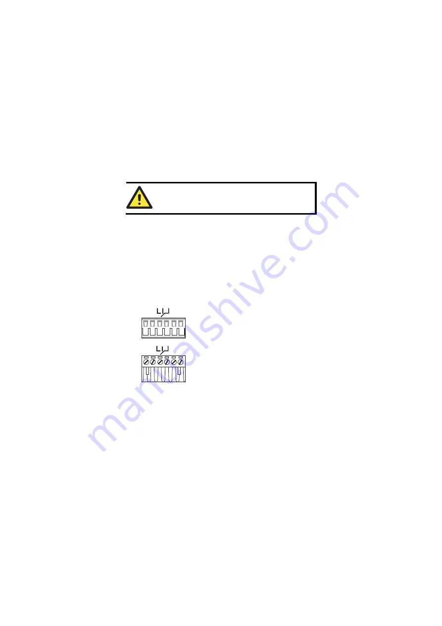
The Alarm Contact consists of the two middle contacts of the terminal block on 
the EDS’s top panel. You may refer to the next section for detailed instructions 
on how to connect the wires to the terminal block connector, and how to attach 
the terminal block connector to the terminal block receptor. 

In this section, we explain the meaning of the two contacts used to connect the 
Alarm Contact. 

FAULT

FAULT

Top View

Front View


FAULT

: The two middle contacts of the 

6-contact terminal block connector are used to 
detect both power faults and port faults. The 
two wires attached to the Fault contacts form 
an open circuit when: 

1.


EDS has lost power from one of the DC 
power inputs. 
 OR 

2.


The PORT ALARM DIP switch for one of 
the ports is set to ON, but the port is not 
connected properly.


If neither of these two conditions is satisfied, 
the Fault circuit will be closed. 


Содержание EtherDevice Switch EDS-G205

Страница 1: ...dware Installation Guide Second Edition April 2009 2009 Moxa Inc All rights reserved Reproduction without permission is prohibited Fl 4 No 135 Lane 235 Pao Chiao Rd Shing Tien City Taipei Taiwan R O C TEL 886 2 8919 1230 P N 1802002051011 ...

Страница 2: ...his Hardware Installation Guide we use EDS as an abbreviation for Moxa EtherDevice Switch EDS Moxa EtherDevice Switch Package Checklist Your EDS is shipped with the following items If any of these items is missing or damaged please contact your customer service representative for assistance y Moxa EtherDevice Switch y Hardware Installation Guide y Moxa Product Warranty booklet Features High Perfor...

Страница 3: ...l View FAULT 1 Grounding screw 2 Terminal block for power input PWR1 PWR2 and relay output 3 Power input PWR1 LED 4 Power input PWR2 LED 5 Fault LED 6 TP port s 10 10 1000 Mbps LED 7 Port number 8 10 100 1000BaseT X Port 9 Model Name 10 DIP switches 11 Heat dissipation orifices 12 Screw hole for wall mounting kit 13 DIN Rail Kit ...

Страница 4: ...ow STEP 1 Insert the top of the DIN rail into the slot just below the stiff metal spring STEP 2 The DIN rail attachment unit will snap into place as shown below metal spring DIN Rail metal spring DIN Rail To remove the DIN rail from the EDS simply reverse Steps 1 and 2 Wall Mounting optional For some applications you will find it convenient to mount the EDS on the wall as illustrated below STEP 1 ...

Страница 5: ...ert the four screw heads through the large parts of the keyhole shaped apertures and then slide the EDS downwards as indicated Tighten the four screws for added stability Wiring Requirements WARNING Safety First Turn the power off before disconnecting modules or wires The proper power supply voltage is listed on the product label Check the voltage of your power source to make sure you are using th...

Страница 6: ...MI Run the ground connection from the ground screw to the grounding surface prior to connecting devices ATTENTION This product is intended to be mounted to a well grounded mounting surface such as a metal panel Wiring the Alarm Contact The Alarm Contact consists of the two middle contacts of the terminal block on the EDS s top panel You may refer to the next section for detailed instructions on ho...

Страница 7: ...e sure the DC power source voltage is stable Communication Connections EDS G205 Models have 5 10 100 1000BaseT X Ethernet ports 10 100 1000BaseT X Ethernet Port Connection The 10 100 1000BaseT X ports located on Moxa EtherDevice Switch s front panel are used to connect to Ethernet enabled devices Most users will choose to configure these ports for Auto MDI MDI X mode in which case the port s pinou...

Страница 8: ...DC DD DD 3 6 1 2 4 5 7 8 3 6 1 2 4 5 7 8 RJ45 8 pin to RJ45 8 pin Cross Over Cable Wiring Cross Over Cable RJ45 Plug Pin 1 Switch Port NIC Port RJ45 Connector RJ45 Connector Tx Tx Rx Rx Rx Rx Tx Tx DC DC DD DD DD DD DC DC Tx Tx Rx Rx Switch Port NIC Port Cable Wiring Rx Rx Tx Tx DC DC DD DD DD DD DC DC 3 6 1 2 4 5 7 8 1 2 3 6 7 8 4 5 Redundant Power Inputs Both power inputs can be connected simult...

Страница 9: ...responding PORT ALARM DIP switch is set to ON is not properly connected If neither of these two conditions occurs the Fault circuit will be closed DIP Switch Settings ON DIP 1 2 3 4 5 2 1 BSP PORT ALARM ON OFF P1 P2 P3 P4 P5 OFF ON The default setting for each DIP switch is OFF The following table explains the effect of setting the DIP switches to the ON positions DIP Switch Setting Description ON...

Страница 10: ...ps link is active Blinking Data is being transmitted at 1000 Mbps 10 100 1000M GREEN Off TP Port s 1000 Mbps link is inactive Auto MDI MDI X Connection The Auto MDI MDI X function allows users to connect the EDS s 10 100 1000BaseT X ports to any kind of Ethernet device without paying attention to the type of Ethernet cable being used for the connection This means that you can use either a straight...

Страница 11: ... it will default to 10 Mbps speed and half duplex mode as required by the IEEE802 3 standard Specifications Specifications and Pin Assignments Technology Standards IEEE 802 3 for 10BaseT IEEE 802 3u for 100BaseT X IEEE 802 3ab for 1000BaseT Interface RJ45 Ports 10 100 1000BaseT X auto negotiation speed LED Indicators PWR1 PWR2 FAULT 10 100M 1000M DIP Switch Port break alarm broadcast storm protect...

Страница 12: ...l 3 EN61000 4 6 CS Level 3 EN61000 4 8 EN61000 4 11 EN61000 4 12 Shock IEC60068 2 27 Free Fall IEC60068 2 32 Vibration IEC60068 2 6 WARRANTY 5 years Technical Support Contact Information www moxa com support Moxa Americas Toll free 1 888 669 2872 Tel 1 714 528 6777 Fax 1 714 528 6778 Moxa China Shanghai office Toll free 800 820 5036 Tel 86 21 5258 9955 Fax 86 10 6872 3958 Moxa Europe Tel 49 89 3 7...

Отзывы: