background image

- 14 - 


NOTE 

You must enable the 

Turbo Ring

 (DIP switch 5) first before 

using the DIP switch to activate the Master and Coupler 
functions. 


NOTE 

If you do not enable any of the EDS switches to be the Ring 
Master, the Turbo Ring protocol will automatically choose the 
EDS switch with the smallest MAC address range to be the Ring 
Master. If you accidentally enable more than one switch to be 
the Ring Master, these switches will auto-negotiate to 
determine which one will be the Ring Master. 


LED Indicators 

The front panel of the Moxa EDS-4009 Series contains several LED 
indicators. The function of each LED is described in the following table: 

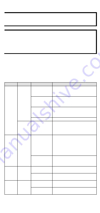
Device LED Indicators 

LED 

Color 

State 

Description 

STATE 

Green 

On 

When system has passed power-
on self-test (POST) and is ready 
to run. 

Blinking 

(1 time/sec) 

Press the reset button for five 
seconds to reset to factory default 
settings 

Blinking 

(4 times/sec) 

When pressing the reset button 
depress for 5 seconds to reset to 
factory default. 

Off 

N/A 

Red 

On 

The system has initially failed the 
boot-up process 


System Info. Read Fail or 
EEPROM information error 

FAULT 

Red 

On 

1.


The relay contact has been 
triggered 

2.


The ingress rate limit has 
been exceeded and the port 
has entered shut down mode 

3.


Invalid Ring port connection 

Off 

When the system boots up and 
runs correctly or a user-
configured event is not triggered. 

P1 

Amber 

On 

Power is being supplied to power 
input PWR. 

Off 

Power is not being supplied to 
power input PWR. 

P2 

Amber 

On 

Power is being supplied to power 
input PWR. 

Off 

Power is not being supplied to 
power input PWR. 

Содержание EtherDevice EDS-4009 Series

Страница 1: ...802040090010 1802040090010 EDS 4009 Series Quick Installation Guide Moxa EtherDevice Switch Version 1 0 March 2022 Technical Support Contact Information www moxa com support 2022 Moxa Inc All rights reserved ...

Страница 2: ...information and software downloads on the relevant product pages located on Moxa s website www moxa com Default Settings IP address 192 168 127 253 Subnet Mask 255 255 255 0 Username admin Password moxa Panel Views of EDS 4009 Series 1 100BaseT X LED indicator 2 10BaseT X LED indicator 3 10 100BaseT X ports port 4 to 9 4 100BaseFX port SC ST type port 1 to 3 5 100BaseFX LED indicator 6 Grounding c...

Страница 3: ... 3 Bottom Panel View 1 microSD card slot currently disabled 2 Reset button 3 DIP switches for Turbo Ring Ring Master and Ring Coupler Mounting Dimensions EDS 4009 3MSC T EDS 4009 3SSC T Models ...

Страница 4: ...of the EDS device when you take it out of the box Mount the EDS device on corrosion free mounting rails that meet the EN 60715 standard Installation STEP 1 Insert the upper lip of the DIN rail into the DIN rail mounting kit STEP 2 Press the EDS device towards the DIN rail until it snaps into place ...

Страница 5: ...ons STEP 1 Remove the DIN rail attachment plate from the rear panel of the EDS device as illustrated in the diagram on the right STEP 2 Mounting the EDS device on a wall requires six screws Use the EDS device with wall mount plates attached as a guide to mark the correct locations of the six screws The heads of the screws should be less than 6 0 mm in diameter and the shafts should be less than 3 ...

Страница 6: ...handle the device ATTENTION In order to ensure reliable operations please make sure the operating temperature of the environment does not exceed the specifications When mounting an EDS device with other operating units in a cabinet without forced ventilation a minimum of 4 cm space on both the left and right of the switch is recommended ATTENTION Safety First Be sure to disconnect the power cord b...

Страница 7: ... wiring from output wiring We advise that you label the wiring to all devices in your system Grounding the Moxa EDS Series Grounding and wire routing help limit the effects of noise due to electromagnetic interference EMI Run the ground connection from the ground screw to the grounding surface prior to connecting devices ATTENTION This product is intended to be mounted to a well grounded mounting ...

Страница 8: ... relay output This relay contact uses two contacts of the terminal block on the EDS s power module Refer to the section for detailed instructions on how to connect the wires to the terminal block connector and how to attach the terminal block connector to the terminal block receptor Relay The two contacts of the 4 pin terminal block connector are used to detect user configured events The two wires...

Страница 9: ... Negative DC or Line Neutral AC wires into the V V or L N terminals respectively STEP 2 To keep the DC or AC wires from pulling loose use a small flat blade screwdriver to tighten the wire clamp screws on the front of the terminal block connector STEP 3 Insert the plastic terminal block connector prongs into the terminal block receptor which is located on the EDS devices right side Wiring the Digi...

Страница 10: ...power module clockwise so that the power digital input and relay output connectors can be moved upwards Step 4 Place the module back on to the EDS device and then fasten the two screws on to the module Communication Connections Each EDS 4009 Series switch has various types of communication ports RJ45 console port RS 232 interface USB storage port type A connector currently disabled microSD card sl...

Страница 11: ...se to configure these ports for Auto MDI MDI X mode in which case the port s pinouts are adjusted automatically depending on the type of Ethernet cable used straight through or cross over and the type of device NIC type or HUB Switch type connected to the port In what follows we give pinouts for both MDI NIC type ports and MDI X HUB Switch type ports We also give cable wiring diagrams for straight...

Страница 12: ...a from device II to device I for full duplex transmission All you need to remember is to connect the Tx transmit port of device I to the Rx receive port of device II and the Rx receive port of device I to the Tx transmit port of device II If you are making your own cable we suggest labeling the two sides of the same line with the same letter A to A and B to B as shown by the following illustration...

Страница 13: ...ork failures in an industrial setting There are five Hardware DIP Switches for Turbo Ring on the bottom panel of the EDS device that can help setup the Turbo Ring easily within seconds If you do not want to use a hardware DIP switch to setup the Turbo Ring you can use a web browser telnet or console to disable this function NOTE Please refer to the Turbo Ring section in User s Manual for more deta...

Страница 14: ...ription STATE Green On When system has passed power on self test POST and is ready to run Blinking 1 time sec Press the reset button for five seconds to reset to factory default settings Blinking 4 times sec When pressing the reset button depress for 5 seconds to reset to factory default Off N A Red On The system has initially failed the boot up process System Info Read Fail or EEPROM information ...

Страница 15: ...tion is enabled 2 The switch is set as the Tail of Turbo Chain Blinking 4 times sec 1 The switch is set as the Tail of Turbo Chain and the Chain has gone down 2 The switch is set as the Turbo Chain s Member Head and the corresponding Tail end Chain port is down Off When the switch disables the coupling or tail role of Turbo Chain System LED Except PWR Green Amber Red Blinking 2 times sec The switc...

Страница 16: ...ted digital input 13 to 30V for state 1 30 to 3V for state 0 Max input current 8 mA Power Pre installed Power Module LV LV T models PWR 100 LV HV HV T models PWR 105 HV I Note The EDS 4009 Series supports modular power supplies The model names and power parameters are determined by the installed power module For example EDS 4009 T PWR 100 LV EDS 4009 LV T EDS 4009 T PWR 105 HV I EDS 4009 HV T If y...

Страница 17: ...03 lb EDS 4009 3SSC T models 932 g 2 05 lb Installation DIN rail mounting wall mounting with optional kit Environmental Limits Operating Temperature 10 to 60 C 14 to 140 F for standard models 40 to 75 C 40 to 167 F for T models Storage Temperature 40 to 85 C 40 to 185 F Ambient Relative Humidity 5 to 95 non condensing Altitude Up to 2000 m Note Please contact Moxa if you require products guarantee...

Страница 18: ...omplies with Part 15 of the FCC rules Operation is subject to the following conditions 1 This device may not cause harmful interference 2 This device must accept any interference received including interference that may cause undesired operation ...

Отзывы: