background image


- 11 - 

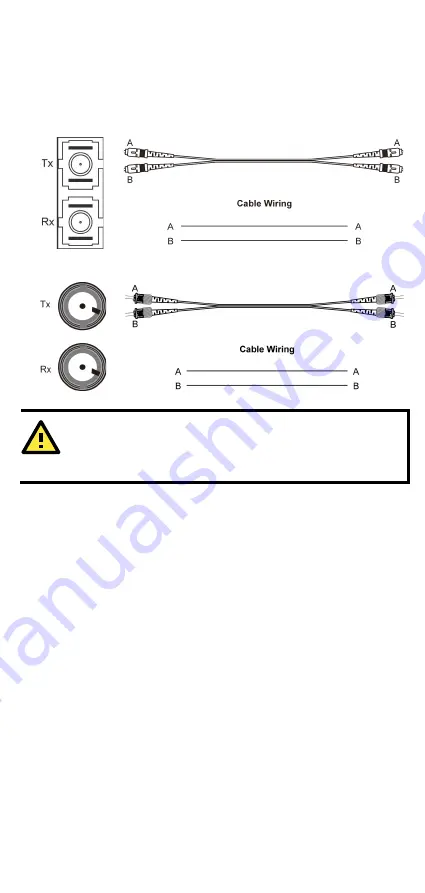
All you need to remember is to connect the Tx (transmit) port of device I 
to the Rx (receive) port of device II, and the Rx (receive) port of device I 
to the Tx (transmit) port of device II. If you make your own cable, we 
suggest labeling the two sides of the same line with the same letter 
(A-to-A and B-to-B, as shown below, or A1-to-A2 and B1-to-B2). 

SC-Port Pinouts 

SC-Port to SC-Port Cable Wiring 


ST-Port Pinouts 

ST-Port to ST-Port Cable Wiring 


ATTENTION 

This is a Class 1 Laser/LED product. To avoid causing serious 
damage to your eyes, do not stare directly into the Laser Beam. 


Redundant Power Inputs 

Both power inputs can be connected simultaneously to live DC power 
sources. If one power source fails, the other live source acts as a backup, 
and automatically supplies all of EDS-316’s power needs. 

Alarm Contact 

Moxa EtherDevice Switch has one Alarm Contact located on the top panel. 
For detailed instructions on how to connect the Alarm Contact power 
wires to the two middle contacts of the 6-contact terminal block 
connector, see the Wiring the Alarm Contact section on page 7. A typical 
scenario would be to connect the Fault circuit to a warning light located in 
the control room. The light can be set up to switch on when a fault is 
detected. 
The Alarm Contact has two terminals that form a Fault circuit for 
connecting to an alarm system. The two wires attached to the Fault 
contacts form an open circuit when (1) EDS has lost power from one of 
the DC power inputs, or (2) The PORT ALARM DIP Switch for one of the 
ports is set to ON, but the port is not connected properly. 
If neither of these two conditions occurs, the Fault circuit will be closed. 

Содержание EDS-316 EtherDevice

Страница 1: ... 2014 Moxa Inc All rights reserved P N 1802003160011 EDS 316 Hardware Installation Guide Moxa EtherDevice Switch Fourth Edition April 2014 ...

Страница 2: ...Device Switch EDS Moxa EtherDevice Switch Package Checklist Moxa EDS 316 is shipped with the following items If any of these items is missing or damaged please contact your customer service representative for assistance Moxa EtherDevice Switch Protective caps for unused ports Hardware Installation Guide Moxa Product Warranty Card Features High Performance Network Switching Technology 10 100BaseT X...

Страница 3: ...y output 3 Heat dissipation orifices 4 DIP switches EDS 316 has 18 DIP switches in total 2 DIP switches are reserved 5 Power input PWR1 LED 6 Power input PWR2 LED 7 Fault LED 8 10 100BaseT X Port 9 TP port s 100 Mbps LED 10 TP port s 10 Mbps LED 11 Model Name 12 Screw hole for wall mounting kit 13 DIN Rail Kit ...

Страница 4: ... DIP switches in total 2 DIP switches are reserved 5 Power input PWR1 LED 6 Power input PWR2 LED 7 Fault LED 8 10 100BaseT X Port 9 TP port s 100 Mbps LED 10 TP port s 10 Mbps LED 11 Model Name 12 100BaseFX Port SSC for EDS 316 MS SC SSC 80 for EDS 316 SS SC 40 80 13 100BaseFX Port MSC for EDS 316 MS SC SSC 40 for EDS 316 SS SC 40 80 14 FX port s 100 Mbps LED 15 Screw hole for wall mounting kit 16...

Страница 5: ...on orifices 4 DIP switches EDS 316 has 18 DIP switches in total 2 DIP switches are reserved 5 Power input PWR1 LED 6 Power input PWR2 LED 7 Fault LED 8 10 100BaseT X Port 9 TP port s 100 Mbps LED 10 TP port s 10 Mbps LED 11 Model Name 12 100BaseFX Port 13 FX port s 100 Mbps LED 14 Screw hole for wall mounting kit 15 DIN Rail Kit ...

Страница 6: ...u need to reattach the DIN Rail attachment plate make sure the stiff metal spring is situated towards the top as shown in the figures below STEP 1 Insert the top of the DIN Rail into the slot just below the stiff metal spring STEP 2 The DIN Rail attachment unit will snap into place as shown below To remove Moxa EtherDevice Switch from the DIN Rail simply reverse Steps 1 and 2 above ...

Страница 7: ...Do not screw the screws in all the way leave about 2 mm to allow room for sliding the wall mount panel between the wall and the screws STEP 3 Once the screws are fixed in the wall insert the four screw heads through the large parts of the keyhole shaped apertures and then slide EDS 316 downwards as indicated Tighten the four screws for added stability ATEX Information 1 Certificate number DEMKO 08...

Страница 8: ...EC 60950 EN60950 or similar regulation WARNING Safety First Be sure to disconnect the power cord before installing and or wiring your Moxa EtherDevice Switch Calculate the maximum possible current in each power wire and common wire Observe all electrical codes dictating the maximum current allowable for each wire size If the current goes above the maximum ratings the wiring could overheat causing ...

Страница 9: ...connect the Alarm Contact FAULT The two middle contacts of the 6 contact terminal block connector are used to detect both power faults and port faults The two wires attached to the Fault contacts form an open circuit when 1 EDS has lost power from one of the DC power inputs OR 2 The PORT ALARM DIP Switch for one of the ports is set to ON but the port is not connected properly If neither of these t...

Страница 10: ...ght through and cross over Ethernet cables 10 100Base T x RJ45 Pinouts MDI Port Pinouts MDI X Port Pinouts 8 pin RJ45 Pin Signal 1 Tx 2 Tx 3 Rx 6 Rx Pin Signal 1 Rx 2 Rx 3 Tx 6 Tx RJ45 8 pin to RJ45 8 pin Straight Through Cable Wiring RJ45 8 pin to RJ45 8 pin Cross Over Cable Wiring 100BaseFX Ethernet Port Connection The concept behind the SC ST port and cable is very straightforward Suppose you a...

Страница 11: ... acts as a backup and automatically supplies all of EDS 316 s power needs Alarm Contact Moxa EtherDevice Switch has one Alarm Contact located on the top panel For detailed instructions on how to connect the Alarm Contact power wires to the two middle contacts of the 6 contact terminal block connector see the Wiring the Alarm Contact section on page 7 A typical scenario would be to connect the Faul...

Страница 12: ...ch LED is described in the table below LED Color State Description PWR1 AMBER On Power is being supplied to power input PWR1 Off Power is not being supplied to power input PWR1 PWR2 AMBER On Power is being supplied to power input PWR2 Off Power is not being supplied to power input PWR2 FAULT RED On When the corresponding PORT alarm is enabled and the port s link is inactive Off When the correspond...

Страница 13: ...es up to 5 km for multi mode and 40 km and 80 km for single mode for installation versatility Dual Speed Functionality and Switching Moxa EDS 316 s 10 100 Mbps switched RJ45 port auto negotiates with the connected device for the fastest data transmission rate supported by both devices All models of Moxa EtherDevice Switch are plug and play devices so that software configuration is not required at ...

Страница 14: ...eans that some nodes could be operating at 10 Mbps while at the same time other nodes are operating at 100 Mbps Auto negotiation takes place when an RJ45 cable connection is made and then each time a LINK is enabled EDS 316 advertises its capability for using either 10 Mbps or 100 Mbps transmission speeds with the device at the other end of the cable expected to similarly advertise Depending on wh...

Страница 15: ...S SC 40 80 EDS 316 MM SC EDS 316 MM ST EDS 316 MS SC EDS 316 MS SC 80 Connection Removable 6 pin Terminal Block Overload Current Protection 1 6 A Reverse Polarity Protection None Mechanical Casing IP30 protection metal case Dimensions 80 5 x 135 x 105 mm W x H x D Weight 0 84 kg Installation DIN Rail Wall Mounting Environmental Operating Temperature 0 to 60 C 32 to 140 F 40 to 75 C 40 to 167 F for...

Страница 16: ... EDS 316 T EDS 316 M SC T EDS 316 M ST T EDS 316 MM SC T EDS 316 MM ST T EDS 316 MS SC T EDS 316 S SC T EDS 316 SS SC T Please check the specifications section for detailed product information Optional Accessories DR 4524 45W 2A DIN Rail 24 VDC Power Supply 85 to 264 VAC input DR 75 24 75W 3 2A DIN Rail 24 VDC Power Supply 85 to 264 VAC input DR 120 24 120W 5A DIN Rail 24 VDC Power Supply 88 to 13...

Отзывы: