background image


A

A


Appendix A


Safety Installation Instructions 

A. RTC Battery Warning 

CAUTION: 

There is a risk of explosion if battery is replaced by an incorrect type. Dispose of 

used batteries according to the instructions. 


B. Fuse Warning 

CAUTION:

 For continued protection against fire, replace only with same type and rating of fuse. 


C. Rackmount Warning 

The following or similar rackmount instructions are included with the installation instructions: 

(1) Elevated Operating Ambient:

 If installed in a closed or multi-unit rack assembly, the 

operating ambient temperature of the rack environment may be greater than the room ambient 
temperature. Therefore, consideration should be given to installing the equipment in an 
environment compatible with the maximum ambient temperature (Tma) specified by the 
manufacturer. 

(2) Reduced Air Flow:

 Installation of the equipment in a rack should be such that the amount of 

air flow required for safe operation of the equipment is not compromised. 

(3) Mechanical Loading:

 Mounting of the equipment in the rack should be such that a hazardous 

condition is not achieved due to uneven mechanical loading. 

(4) Circuit Overloading:

 Consideration should be given to the connection of the equipment to the 

supply circuit and the effect that overloading of the circuits might have on overcurrent protection 
and supply wiring. Appropriate consideration of equipment nameplate ratings should be used 
when addressing this concern. 

(5) Reliable Grounding:

 Reliable grounding of rack-mounted equipment should be maintained. 

Particular attention should be given to supply connections other than direct connections to the 
branch circuit (e.g., by using power strips). 


Содержание DA-682 Series

Страница 1: ...DA 682 Series Embedded Computer Hardware User s Manual First Edition May 2008 www moxa com product 2008 Moxa Inc all rights reserved Reproduction without permission is prohibited ...

Страница 2: ...e Moxa reserves the right to make improvements and or changes to this manual or to the products and or the programs described in this manual at any time Information provided in this manual is intended to be accurate and reliable However Moxa assumes no responsibility for its use or for any infringements on the rights of third parties that may result from its use This product might include unintent...

Страница 3: ...r 2 3 Reset Button 2 3 Front Panel LED 2 4 Connecting to a Display 2 4 Connecting a PS 2 Keyboard and Mouse 2 5 Connecting USB Devices 2 6 Gigabit LAN Ports 2 6 Upgrading the Memory Module 2 7 Installing a CompactFlash Card 2 11 Installing a SATA Hard Disk 2 13 Inserting and Removing Expansion Modules 2 17 DA SP08 I DB DA SP08 DB Serial Expansion Modules 2 17 DA SP08 I TB Serial Expansion Module 2...

Страница 4: ...ce 3 11 Onboard GigaLan Control 3 12 Onboard I O Chip Setup 3 12 Power 3 13 Wake Up Control 3 13 Hardware Monitor 3 15 Load Defaults 3 15 Exiting the BIOS Setup 3 16 Upgrading the BIOS 3 17 Appendix A Safety Installation Instructions A 1 ...

Страница 5: ...stallation connector interfaces and BIOS setup of the DA 682 For software configuration and management please refer to the user s manual for your operating system This chapter covers the following topics Overview Model Descriptions and Package Checklist Appearance Dimensions Features Hardware Block Diagram DA 682 Basic System DA SP08 I DB Serial Port Expansion Module DA LN04 RJ LAN Port Expansion ...

Страница 6: ...ounted rugged enclosure This robust rack mountable design provides the hardened protection needed for industrial environment applications Model Descriptions and Package Checklist The DA 682 Series includes the following models y DA 682 CE DA 682 basic system VGA 4 Gigabit LANs USB x 4 CompactFlash socket 256 MB system memory 256 MB WinCE 6 0 pre installed flash disk module y DA 682 LX DA 682 basic...

Страница 7: ...ew 10 100Mbps Ethernet Port LAN1 LAN2 LAN3 LAN4 P1 P2 P3 P4 P5 P6 P7 P8 Gigabit Ethernet LAN1 LAN3 LAN2 LAN4 Module A Module B Power Input 100 240 VAC ON OFF RS 232 422 485 RS 232 422 485 Module Slot A Module Slot B Power Input 100 240 VAC USB 2 0 Host x 2 VGA PS 2 10 100 1000 Mbps Ethernet x 4 10 100 Mbps Ethernet x 4 DA SP08 I DB DA LN04 RJ Power Switch RS 232 422 485 Serial Port x 8 ATTENTION E...

Страница 8: ... 1GHz processor with 400 533 MHz FSB y Intel 915GME ICH6M chipset y 200 pin DDR2 SODIMM socket x1 supporting DDR2 400 533 up to 1 GB y 4 Gigabit Ethernet ports for network redundancy y 1 CompactFlash socket y 1 SATA connector for storage expansion y USB 2 0 ports for high speed peripherals y 2 expansion module slots for I O expansion y 19 inch rackmount 2U height form factor y Fanless design y 100...

Страница 9: ... 10 100 Mbps Ethernet ports ATTENTION Refer to the Non standard Baudrates section for instructions on how to calculate which baudrates are supported Hardware Block Diagram DA 682 Basic System 1 5 RS 232 422 485 Serial Ports or 10 100 Mbps LAN Ports Gigabit LAN Ports Intel Celeron M 1GHz CPU VGA Power LAN1 RTC LAN2 Watch Dog Intel 915 GME North Bridge Intel ICH6 South Bridge Expansion Module A Expa...

Страница 10: ...8 P5 P6 P3 P4 I1 I2 I7 I8 I5 I6 I3 I4 Isolation Circuit DB9 Connector PCI Bus to DA 682 Basic System RS 232 422 485 DA LN04 RJ LAN Port Expansion Module PCI Bridge RJ45 Connector PCI Bus to DA 682 Basic System 10 100 Mbps LAN Ports Realtek RTL8100 Realtek RTL8100 Realtek RTL8100 Realtek RTL8100 LAN1 LAN2 LAN3 LAN4 1 6 ...

Страница 11: ...DDR2 400 533 512 MB max CompactFlash Socket available for storage expansion with DMA mode support Other Peripherals USB USB 2 0 compliant hosts x 4 Type A connector supports system boot up KB MS 1 PS 2 interface support standard PS 2 keyboard and PS 2 mouse via Y type cable 0ptional Display Graphics Controller Integrated graphics with built in Intel 915GME and built in Intel extreme Graphics 2 tec...

Страница 12: ... 3 54 in Mounting Standard 19 inch rackmount Switches and Buttons Power Switch on off on rear panel Reset Button To reset system hardware on front panel Environmental Limits Operating Temperature 10 to 60 C 14 to 140 F Operating Humidity 5 to 95 RH Storage Temperature Standard Models 20 to 80 C 4 to 176 F Power Requirements Input Voltage 100 to 240 VAC VDC auto ranging 47 to 63 Hz for AC input Pow...

Страница 13: ... 15 KV ESD and 2 KV isolation protection for all signals Serial Signals RS 232 TxD RxD DTR DSR RTS CTS DCD GND TxD RxD DTR DSR RTS CTS DCD GND TxD RxD RTS CTS GND RS 422 TxD TxD RxD RxD GND 4 wire RS 485 TxD TxD RxD RxD GND 2 wire RS 485 Data Data GND Data bits 5 6 7 8 Stop bits 1 1 5 2 Parity None Even Odd Space Mark Flow Control RTS CTS XON XOFF RS 485 ADDCTM ATTENTION Refer to the Non standard ...

Страница 14: ...lowing formula to calculate which baudrates are supported by the DA 283 A Baudrate 921600 N M 8 bps for N 1 2 18431 M 0 1 2 7 or B Baudrate 8 x 921600 K bps for K 8 9 147456 If you are a programmer and you need to write a driver for your serial device then you may need to use formula A If you have a serial device that requires using a non standard baudrate then you can use formula B to determine i...

Страница 15: ...115200 8 0 1200 768 0 57600 16 0 600 1536 0 38400 24 0 300 3072 0 19200 48 0 150 6144 0 9600 96 0 75 12288 0 7200 128 0 50 18432 0 1 11 WARNING Communication between a serial device and a Moxa UART port may not work correctly if the serial device uses a baudrate that it not within the correct tolerance of a baudrate calculated from either formula A or formula B ...

Страница 16: ... time to application development This chapter describes hardware installation and connector interfaces of the DA 682 embedded computers This chapter covers the following topics Placement Options Desktop Rack mounting Wiring Requirements Connecting the Power Reset Button Front Panel LED Connecting to a Display Connecting a PS 2 Keyboard and Mouse Connecting USB Devices Gigabit LAN Ports Upgrading t...

Страница 17: ...cross make sure the wires are perpendicular at the intersection point y You can use the type of signal transmitted through a wire to determine which wires should be kept separate The rule of thumb is that wiring that shares similar electrical characteristics can be bundled together y Keep input wiring and output wiring separate y When necessary it is strongly advised that you label wiring to all d...

Страница 18: ...dule B Module A Gigabit Ethernet 100 Mbps 1000 Mbps 100 Mbps 10 Mbps TX RX Green Orange Serial Port LAN Port 10 100Mbps Ethernet Port LAN1 LAN2 LAN3 LAN4 P1 P2 P3 P4 P5 P6 P7 P8 Gigabit Ethernet LAN1 LAN3 LAN2 LAN4 Module A Module B Power Input 100 240 VAC ON OFF RS 232 422 485 RS 232 422 485 Power Switch 110 240V AC Power In Reset Button Pressing the Reset button initiates a hardware warm reboot ...

Страница 19: ...0 Mbps Gigabit Ethernet mode Gigabit LAN LEDs 1 4 Off No operation or 10 Mbps Ethernet mode Green 100 Mbps Ethernet mode or TX signal of serial port is active Yellow 10 Mbps Ethernet mode or RX signal of serial port is active Module A LEDs 1 8 Off No operation Green 100 Mbps Ethernet mode or TX signal of serial port is active Yellow 10 Mbps Ethernet mode or RX signal of serial port is active Modul...

Страница 20: ...is 6 pin mini DIN connector has the pin assignments shown below 10 100Mbps Ethernet Port LAN1 LAN2 LAN3 LAN4 P1 P2 P3 P4 P5 P6 P7 P8 Gigabit Ethernet LAN1 LAN3 LAN2 LAN4 Module A Module B Power Input 100 240 VAC ON OFF RS 232 422 485 RS 232 422 485 PS 2 Keyboard Mouse Pin No Signal Definition 1 PS 2 Keyboard Data 2 PS 2 Mouse Data 3 GND 4 VCC 5 PS 2 Keyboard Clock 6 PS 2 Mouse Clock Use the Y type...

Страница 21: ...s in detail DA 682 Industrial Embedded Computer Module B Module A Gigabit Ethernet 100 Mbps 1000 Mbps 100 Mbps 10 Mbps TX RX Green Orange Serial Port LAN Port USB 2 0 Host x 2 10 100Mbps Ethernet Port LAN1 LAN2 LAN3 LAN4 P1 P2 P3 P4 P5 P6 P7 P8 Gigabit Ethernet LAN1 LAN3 LAN2 LAN4 Module A Module B Power Input 100 240 VAC ON OFF RS 232 422 485 RS 232 422 485 USB 2 0 Host x 2 Gigabit LAN Ports The ...

Страница 22: ...s Default IPAddress Netmask LAN 1 192 168 3 127 255 255 255 0 LAN 2 192 168 4 127 255 255 255 0 LAN 3 192 168 5 127 255 255 255 0 LAN 4 192 168 6 127 255 255 255 0 Upgrading the Memory Module The DA 682 embedded computer supports one 200 pin DDR2 400 533 SODIMM module up to 1 GB One DDR2 SDRAM memory module is installed at the factory To upgrade the DDR2 SDRAM memory module follow these instructio...

Страница 23: ...ware Installation 3 After removing the memory module cover you should see the DDR2 SDRAM module Memory Module Cover Factory installed DDR2 SDRAM module 4 Carefully remove and replace the memory module Be sure to orient the module correctly 2 8 ...

Страница 24: ...DA 682 Series Hardware User s Manual Hardware Installation 2 9 ...

Страница 25: ...DA 682 Series Hardware User s Manual Hardware Installation Orient the memory module correctly 5 Replace the DA 682 memory module cover 2 10 ...

Страница 26: ... these instructions 1 Disconnect the DA 682 from its power source 2 The DA 682 s CompactFlash socket is located on the right side of front panel Unscrew the CompactFlash socket cover CF Socket Cover Unscrew the CF socket cover 3 There is a tenon hook on the cover of CF socket Turn the CompactFlash card over and then insert the CompactFlash card into the tenon hook of CF socket cover 2 11 ...

Страница 27: ...ard into Tenon hook of CF socket cover ATTENTION Be careful of how you orient the CompactFlash card You should turn the CF card bottom side up in order to hook CF card into CF socket cover 4 Gently insert the CompactFlash card into the CF socket making sure that the card is oriented correctly 2 12 ...

Страница 28: ...nP Plug and Play functions It is necessary to remove power source first before inserting or removing the CompactFlash card Installing a SATA Hard Disk The DA 682 embedded computer has one SATA connector for installing a SATA hard disk To install a 2 5 inch SATA hard disk follow these instructions 1 Disconnect the DA 682 from its power source 2 13 ...

Страница 29: ...allation 2 Open the top cover of the DA 682 A hard disk bracket is located on the right side of the DA 682 SATA Connector Hard Disk Bracket Hard Disk Power Connector 3 Remove hard disk bracket 4 Install the SATA hard disk in the hard disk bracket 2 14 ...

Страница 30: ...DA 682 Series Hardware User s Manual Hardware Installation 5 Next install the SATA hard disk and hard disk bracket back into the DA 682 2 15 ...

Страница 31: ...DA 682 Series Hardware User s Manual Hardware Installation 6 Connect the SATA disk cable and power cable to the SATA hard disk SATA Power Cable SATA Disk Cable 2 16 ...

Страница 32: ...xpansion module A or module B on the rear panel 3 Carefully insert or remove the expansion module by pushing or pulling on the two screws at the same time By pushing or pulling on the two screws evenly you can ensure that the board is inserted or removed without being damaged Push or pull the two screws evenly at the same time DA SP08 I DB DA SP08 DB Serial Expansion Modules The DA SP08 I DB and D...

Страница 33: ...as 8 software selectable isolated serial ports with 5 pin terminal blocks Each port can be configured by software for RS 232 RS 422 or RS 485 RS 232 422 485 P1 P2 P3 P4 P5 P6 P7 P8 The pin assignments for the ports are shown in the following table Pin RS 422 RS 485 2 wire RS 232 1 TXD TXD 2 TXD RXD 3 RXD DATA RTS 4 RXD DATA CTS 5 GND GND GND DA LN04 RJ LAN Expansion Module The DA LN04 RJ LAN expan...

Страница 34: ...he ports are shown in the following table 2 19 8 1 Pin No Signal Definition 1 TX 2 TX 3 RX 4 5 6 RX 7 8 There are two LEDs on each RJ45 port for indicating the status of the port LED Color Description Green 100 Mbps Ethernet mode Yellow 10 Mbps Ethernet mode RJ45 Connector Off Inactive ...

Страница 35: ...tions will be stored in the battery backed up CMOS RAM which retainsthe system information after system reboots or the power is removed This chapter covers the following topics Entering the BIOS Setup Utility Modifying the BIOS Main Settings Basic Configuration System Security Advanced Settings Hard Disk Boot Priority Advanced BIOS Features CPU Features Advanced Chipset Settings PnP PCI Configurat...

Страница 36: ...the other hot keys listed below F1 General Help F5 Previous Value F6 Default Settings F7 Turbo Settings F10 Save ESC Exit Modifying the BIOS Main Settings Basic Configuration After entering the BIOS Setup or choosing the Main option the BIOS main menu will be displayed Use this menu to check the basic system information such as memory and IDE hard drive You can also use the menu for configuring ba...

Страница 37: ...assword is disabled the system will boot and you can enter the BIOS Setup Menu without entering a password Once a password has been set you will be prompted to enter the password each time you enter Setup This prevents unauthorized persons from changing any part of your system configuration In addition when a password setting is enabled you can set up the BIOS to request a password each time the s...

Страница 38: ...evices will be searched in order to find a boot device The available options are CDROM default for first boot device Removable default for third boot device Hard Disk default for second boot device and Disabled Boot Other Devices This setting allows the system to try to boot from other devices if the system fails to boot from the 1st 2nd or 3rd boot devices The options are Enabled default and Disa...

Страница 39: ... System performance may degrade if you disable this item Options Enabled default Disabled Quick Power on Self Test This setting allows the system to skip certain tests while the system boots up Enable this feature to speed up the boot up process Options Enabled default Disabled Boot Up NumLock Status Selects the power on state for NumLock Options On default Numpad keys are number keys Off Numpad k...

Страница 40: ...ve or inactive Options Disabled Enabled default MPS Version Control for OS Set the Multi Processor Specification 1 1 was the original specification MPS version 1 4 adds extended configuration tables for improved support for multiple PCI bus configurations and greater expandability In addition MPS 1 4 introduces support for a secondary PCI bus without requiring a PCI bridge Options 1 1 1 4 default ...

Страница 41: ... Options Enabled default Disabled Video BIOS Cacheable Enabling this feature allows the caching of the video BIOS and may improve performance A system error could occur if another program writes to this memory cache area Options Enabled Disabled default Memory Hole at 15M 16M When enabled the system will reserve a system memory area for the ISA adapter ROM and this memory area will not be availabl...

Страница 42: ...FIXED Memory Size Sets the maximum amount of system memory that can be allocated as graphics memory Options 64 MB 128 MB default PnP PCI Configurations Init Display First This item allows you to decide whether the PCI interface or onboard graphic chip is activated first Options PCI default Onboard Resources Controlled By The BIOS can automatically configure all boot and Plug and Play compatible de...

Страница 43: ...uch as graphics accelerators or MPEG video cards Options Disabled default Enabled PCI Latency Timer CLK Configure PCI Latency Time to optimize the PCI speed The range of possible values is 0 to 255 with a default value of 32 Frequency Voltage Control Spread Spectrum Select Enabled to reduce EMI Electromagnetic Interference The default is Enabled Peripherals 3 9 ...

Страница 44: ...nel 0 1 Master Slave PIO The IDE PIO Programmed Input Output fields let you set a PIO mode 0 4 for each of the IDE devices that the onboard IDE interface supports Modes 0 to 4 will increase performance incrementally In Auto mode the system automatically determines the best mode for each device Options Auto default Mode0 Mode1 Mode2 Mode3 Mode4 IDE Channel 0 1 Master Slave UDMA Ultra DMA functional...

Страница 45: ...troller This feature allows you to enable disable the USB 2 0 controller Options Enabled default Disabled USB Keyboard Support This item is useful for DOS systems Enable it if you want to use a USB keyboard under a DOS environment Options Enabled Disabled default Onboard LAN Boot ROM Decide whether to invoke the boot ROM of the onboard LAN chip Options Enabled Disabled default 3 11 ...

Страница 46: ...A 682 Series Hardware User s Manual BIOS Setup Onboard GigaLan Control GigaLan 1 2 3 4 Used to Enable Disable the onboard Giga LAN controller Options Enabled default Disabled Onboard I O Chip Setup 3 12 ...

Страница 47: ... you select Former Sts Forrner Status the system will boot or not depending on the status before the power failure Options Off On default Former Sts Power The Power Setup Menu allows you to configure your system power up power down options Soft Off by PWR BTTN Select the Instant Off option if you would like the system to power down immediately after pushing the power button Selecting the Delay 4 S...

Страница 48: ...ed default PCI PCIE RTC Wake Up When Enabled you can set the date and time at which the RTC real time clock alarm awakens the system from Suspend mode Options Disabled default Enabled Date of Month Alarm Set the date for the RTC Wake Up function when RTC Wake Up is set to Enabled Time hh mm ss Alarm You can set the hour minute and second of the RTC Wake Up function when RTC Wake Up is set to Enabl...

Страница 49: ...an this setting the system will throttle down to 75 When the CPU temperature is higher than this setting plus 10 C the system will throttle down to 50 Options 80 C 176 F 90 C 194 F default 100 C 212 F Disabled Warning Beep Set the beep to sound or not sound when the CPU temperature is over the CPU warning temperature Options Disabled default Enabled Load Defaults 3 15 ...

Страница 50: ...ble please load the system default settings Load CMOS from BIOS Use this option to load BIOS settings from flash ROM to CMOS Save CMOS to BIOS Use this option to save the BIOS settings from the CMOS to flash ROM Exiting the BIOS Setup To exit the BIOS setup utility choose Exit Pressing ESC will achieve the same result Save Exit Setup Save all configuration changes to CMOS memory and exit setup A c...

Страница 51: ...os org kernel 2 Copy DOS system files kernel sys and command com to a specified directory C FreeDOS in this example 3 Start the HP USB Disk Storage Format Tool and select the USB device that you want to use as a bootable disk in the Device drop down box 4 Select FAT in the File system drop down box 5 Type the disk name in the Volume label field 6 Check the option Create a DOS startup disk under fo...

Страница 52: ...m the following website http gocoding com page php al bootflashdos Step 2 Prepare the Upgrade Tool and BIOS Binary File You must use the BIOS upgrade installation file to upgrade the BIOS You can download it from the Moxa Download Center at http web4 moxa com support download_center asp 1 Get the BIOS upgrade installation file The file name should have following format BIOS_DA 68X_V1 0_Build_08042...

Страница 53: ...ct Advanced Æ Hard Disk Boot Priority and then press Enter 4 From the Setup menu use or to select the USB device 5 Press to move it up to the first priority and press Esc to exit the setup menu 6 Make sure the first boot device is Hard Disk If it isn t press Enter to change it 7 Select Exit Æ Save Exit Setup and then press Enter 8 Choose Y to save to the CMOS and then exit 3 19 ...

Страница 54: ...sk 2 Run awdflash xxxxxxx Sxx from the command line to upgrade the BIOS Replace xxxxxxx Sxx with the BIOS binary file name discussed in Step 2 3 Press F1 to reset the system after the bios update is complete The system should reboot at this time ATTENTION Do NOT switch off the power supply during the BIOS upgrade since doing so may cause the system to crash 3 20 ...

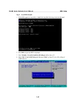
Страница 55: ...grade is successful it should reboot and the following screen should appear 2 Press DEL to open the BIOS Setup menu 3 Select Defaults Æ Load System Default Settings and then choose Y 4 Select Exit Æ Save Exit Setup and then press Enter to choose Y to save the settings to CMOS and exit 3 21 ...

Страница 56: ...DA 682 Series Hardware User s Manual BIOS Setup 3 22 ...

Страница 57: ...th the maximum ambient temperature Tma specified by the manufacturer 2 Reduced Air Flow Installation of the equipment in a rack should be such that the amount of air flow required for safe operation of the equipment is not compromised 3 Mechanical Loading Mounting of the equipment in the rack should be such that a hazardous condition is not achieved due to uneven mechanical loading 4 Circuit Overl...

Отзывы: