background image

DA-661/662/663 Hardware User’s Manual 

Hardware Connection Description 

You should observe the following common wiring rules: 

y


Use separate paths to route wiring for power and devices. If power wiring and device wiring 
paths must cross, make sure the wires are perpendicular at the intersection point. 

NOTE:

 Do not run signal or communication wiring and power wiring in the same wire conduit. 

To avoid interference, wires with different signal characteristics should be routed separately. 

y


You can use the type of signal transmitted through a wire to determine which wires should be 
kept separate. The rule of thumb is that wiring that shares similar electrical characteristics can 
be bundled together. 

y


Keep input wiring and output wiring separate. 

y


Where necessary, it is strongly advised that you label wiring to all devices in the system. 

Connecting the Power 

To power on the DA-661/662/663, use the power cord comes with the product to connect the 
power line to the DA-661/662/663’s AC power connector. The power connector is located on the 
right side of the rear panel. Next, turn on the power switch. The DA-661/662/663 takes about 30 
seconds to boot up. Once the device is ready, the Ready LED on the front panel will light up, and 
the DA-661/662/663 model name and firmware version will appear on the LCD screen. 

Connecting to the Network 

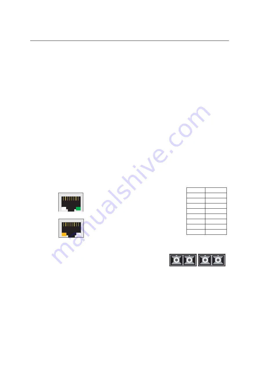
For DA-661 and DA-662, connect one end of the Ethernet cable to one of the DA-661/662’s 
10/100M Ethernet ports (8-pin RJ45) and the other end of the cable to the Ethernet network. If the 
cable is properly connected, the DA-661/662 will indicate a valid connection to the Ethernet in the 
following ways: 

1

8


The lower right corner LED indicator in the lower right 
corner glows a solid green color when the cable is 
properly connected to a 100 Mbps Ethernet network. 
The LED will flicker when Ethernet packets are being 
transmitted or received. 

1

8


The lower left corner LED indicator glows a solid 
orange color when the cable is properly connected to a 
10 Mbps Ethernet network. The LED will flicker when 
Ethernet packets are being transmitted or received. 

Pin Signal 

1 ETx+ 
2 ETx- 
3 ERx+ 
4 --- 
5 --- 
6 ERx- 
7 --- 
8 --- 


For DA-663, connect one end of the fiber channel cable (SC 
connector) to one of the DA-663’s 100BaseFX fiber channel 
ports (either FX1 or FX2). The LED indicators on the front 
panel indicate the operation status. When the fiber channel 
cable is connected, the green light will glow a steady green. 
When data is being transmitted, the green light will flicker. 

TX

FX 1

FX 2

RX

TX

RX


3-3

Содержание DA-661

Страница 1: ...DA 661 662 663 Hardware User s Manual Fifth Edition April 2009 www moxa com product 2009 Moxa Inc All rights reserved Reproduction without permission is prohibited...

Страница 2: ...erves the right to make improvements and or changes to this manual or to the products and or the programs described in this manual at any time Information provided in this manual is intended to be acc...

Страница 3: ...are Block Diagram 2 4 DA 661 2 4 DA 662 DA 662 I 2 5 DA 663 2 5 LED Indicators 2 6 Reset Button 2 6 LCD Screen 2 7 Push Buttons 2 7 Real time Clock 2 7 Chapter 3 Hardware Connection Description 3 1 Pl...

Страница 4: ...Ethernet channels The casing is a standard 1U 19 inch wide rack mounted rugged enclosure The robust rack mountable mechanism design provides the hardened protection needed for industrial environment...

Страница 5: ...power lines Because of the no hard disk fan less energy efficient design the DA 661 662 663 minimize heat generation can operate around the clock year in and year out in heavy duty harsh industrial en...

Страница 6: ...x WinCE 5 0 platform y Robust fanless design y PCMCIA for wireless LAN expansion supports 802 11b g y CompactFlash for storage expansion y USB 2 0 host Hardware Specifications DA 661 DA 662 DA 662 I D...

Страница 7: ...198 45 mm without rack mount ears DA 662 I 480 224 45 mm with rack mount ears 440 224 45 mm without rack mount ears Weight DA 661 2 5 kg DA 662 2 6 kg DA 662 I 2 94 kg DA 663 2 5 kg Operating Temperat...

Страница 8: ...ess operation With the reliable and stable hardware platform that is provided you may devote your attention to the development of your application In this chapter learn the basics about the embedded c...

Страница 9: ...ON OFF Switch 10 100 Mbps Ethernet RJ45 x 2 RS 232 Console Port RS 232 422 485 Serial Ports x 16 RJ45 50 bps to 921 6 Kbps DA 662 DA 662 I Front View LCM Display Panel 19 inch Rackmount Ear Reset But...

Страница 10: ...r Optical Connector 1 2 3 4 5 6 7 8 9 10 11 12 13 14 15 16 Console RS 232 422 485 TX FX1 100 240 VAC VDC Power Input FX2 RX TX RX Power Input 100 240 VAC VDC ON OFF Switch RS 232 Console Port RS 232 4...

Страница 11: ...USB PCMCIA CF LAN Hardware Block Diagram The following block diagrams show the layout of the DA 661 662 663 s internal components DA 661 PCI Bus Console LAN2 LAN1 2 3 2 S R Ethernet Power circuit LCM...

Страница 12: ...Moxa UART ASIC USB Host Ethernet C A M Y H P C A M Y H P Y H P Y H P PCMCIA CF XScale IXP425 533 MHz 32 MB Flash 128 MB SDRAM 3 N A L 4 N A L 1 N A L 2 N A L DA 663 PCI Bus Console FX2 FX1 2 3 2 S R...

Страница 13: ...load the factory default configuration After the factory default configuration has been loaded the system will reboot automatically The Ready LED will blink on and off for the first 5 seconds and then...

Страница 14: ...uttons are MENU up cursor down cursor and SEL Button Action MENU Displays the main menu Scrolls up through a list of items shown on the LCD screen s second line Scrolls down through a list of items sh...

Страница 15: ...r covers the following topics Placement Options Desktop Connecting the Power Connecting the Hardware Wiring Requirements Connecting the Power Connecting to the Network Connecting to a Serial Device Co...

Страница 16: ...661 662 663 to the front of the rack Each L shaped plate has 6 holes leaving two outer or inner holes open for your convenience Connecting the Hardware This section describes how to connect the DA 661...

Страница 17: ...nce the device is ready the Ready LED on the front panel will light up and the DA 661 662 663 model name and firmware version will appear on the LCD screen Connecting to the Network For DA 661 and DA...

Страница 18: ...Card 32 card standard and 16 bit PCMCIA 2 1 JEIDA4 2 card standard It supports 3 3V 5V and 12V at a working voltage of 120 mA 1100 mA The wireless LAN card is optional The wireless LAN card provided...

Отзывы: