

– 4 –
– 5 –
– 6 –
www.moxa.com/support
The Americas: +1-714-528-6777 (toll-free: 1-888-669-2872)
Europe: +49-89-3 70 03 99-0
Asia-Pacific: +886-2-8919-1230
China: +86-21-5258-9955 (toll-free: 800-820-5036)
2014 Moxa Inc., All Rights Reserved
Connecting the Power
AC:
Connect the CN2600 100-240 VAC power line with its AC
connector. If the power is properly supplied, the “Ready” LED will
show a solid red color until the system is ready, at which time the
“Ready” LED will change to a green color.
DC:
Connect the NPort CN2650I-HV’s power cord to the DC
connector, and then follow the steps given below:
Take the CN2650I-8-HV-T as an example. Loosen
the screws on the V+ and V- terminals of the
CN2650I-8-HV-T terminal block. Connect the
power cord’s 100 VDC wire to the terminal block’s V+ terminal, and
the power cord’s DC Power Ground wire to the terminal block’s V-
terminal, and then tighten the terminal block screws. (Note: The
CN2650I-8-HV-T can still operate even if the DC Power Ground
wires are reversed.) The “Ready” LED will show a solid red color
until the system is ready, at which time it will change to a green
color.
Grounding the CN2650I-HV:
Grounding and wire routing help limit the effects
of noise due to electromagnetic interference
(EMI). Run the ground connection from the
ground screw to the grounding surface prior to
connecting devices. The Shielded Ground
(sometimes called Protected Ground) contact is the second contact
from the right of the 5-pin power terminal block connector located
on the rear panel of the CN2650I-8-HV-T. Connect the SG wire to
the Earth ground.
Connecting to the Network
Use an Ethernet cable to connect the CN2600 to the Ethernet
network. There are 2 LED indicators located on the top left and
right corners of the Ethernet connector. If the cable is properly
connected, the CN2600 will indicate a valid connection to the
Ethernet in the following ways:
The top right corner LED indicator maintains a solid
green color when the cable is properly connected to a
100 Mbps Ethernet network.
The top left corner LED indicator maintains a solid
orange color when the cable is properly connected to a
10 Mbps Ethernet network.
Connecting to a Serial Device
Connect the serial data cable between the CN2600 and the serial
device.
Connecting to a Console
A console is a combination of keyboard and monitor, and is used to
configure settings and to monitor the status of your system. If you
do not have a network environment, use a terminal, a PC running
UNIX, or a PC with terminal emulation software (e.g.,
HyperTerminal in Windows; PComm by Moxa). Use an
RJ45-to-DB25 or RJ45-to-DB9 cable to connect the terminal to the
console socket. Refer to the CN2600 User’s Manual for more
details.
Software Installation
Entering the Console Utility
The Console Utility is the main application needed to set up the
server/port configuration, and to execute utilities such as ping,
diagnosis, monitor, and upgrade. There are two ways to enter the
Console Utility. One is to use terminal emulation through a console
terminal, and the other is to telnet from a network terminal.
Refer to the CN2600 User’s Manual for more details.
Pin Assignments and Cable Wiring
10/100BaseTX Port Pinouts Console Port Pinouts
Pin Signal
1
Tx+
2
Tx-
3
Rx+
6
Rx-
Pin RS-232
1 DSR (in)
2 RTS (out)
3
GND
4 TxD (out)
5 RxD (in)
6 DCD (in)
7
CTS (in)
8 DTR (out)
RJ45 RS-232/422/485 Port
Pin RS-232
RS-422/
RS-485-4w
RS-485-2w
1
DSR (in)
–
–
2 RTS (out)
TxD+
–
3
GND
GND
GND
4 TxD (out)
TxD-
–
5
RxD (in)
RxD+
Data+
6
DCD (in)
RxD-
Data-
7
CTS (in)
–
–
8 DTR (out)
–
–
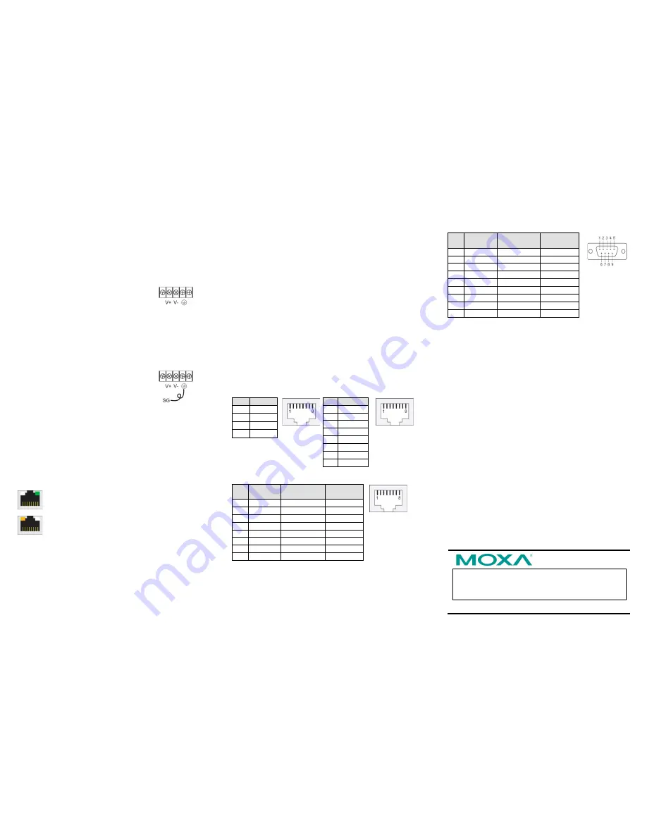
DB9 (male) RS-232/422/485 Port
Pin RS-232
RS-422/
RS-485-4w RS-485-2w
1
DCD
TxD-(A)
–
2
RxD
TxD+(B)
–
3
TxD
RxD+(B)
Data+(B)
4
DTR
RxD-(A)
Data-(A)
5
GND
GND
GND
6
DSR
–
–
7
RTS
–
–
8
CTS
–
–
9
–
–
–


