FORWARD / REVERSE CONTROL BUTTON
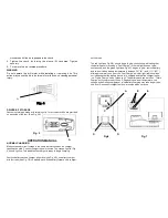
A forward/reverse control button determines the direction of the tool and also
serves as a lock off button. To select forward rotation,
RELEASE THE TRIGGER
SWITCH
(see Fig. 1A), and depress the forward/reverse control button (see Fig.
1B), toward left side of the tool. To select reverse, depress the forward/reverse
control button (see Fig. 1B), toward right side of the tool.
The center position
of the control button
(see Fig.1B)
locks the tool in the off position.
When
change the position of the control button, making sure the trigger is released.
NOTE:
The first time the tool is run after changing the direction of rotation, you
may hear a click on start up. This is normal and does not indicate a problem.
TORQUE ADJUSTMENT COLLAR
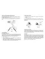
The clutch feature of your Driver/Drill is an adjustable torque screwdriver
mechanism for driving and removing a wide array of fastener shapes and sizes
(see Fig. 2)
. The clutch allows you to instantaneously regulate the torque,
based on the force applied.
F
OR THE DRILL DRIVER
:
Circling the collar are numbers ranging from 1 to 23 and a drill bit symbol.
These numbers are used to set the clutch to deliver a torque range. The higher
number on the collars, the higher torque and larger the fastener which can be
driven. To select any of the numbers, rotate until the desire number aligns with
the selector.
DUAL RANGE GEARING
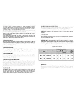
The dual range feature of your Driver/Drill allows you to shift gears for greater
versatility. To select the low speed, high torque setting
(position L)
, turn the
tool off and permit to stop. Push the button forward towards the chuck
(see Fig.
3)
. To select the high speed, low torque setting
(position H)
, turn the tool off
and permit to stop. Slide the gear shifter back (away from chuck).
N
OTE
: Do not change gears when the tool is running. If you are having trouble
changing gears, make sure that the dual range gear button is either completely
pushed forward or completely pushed back.
CLUTCH LOCK
To lock the clutch for drilling operations, simply move the Driver/Drill selector to
the “Drill” position as described under “Operation as a Drill”
This symbol indicates the
DRILL POSITION
. To select this mode for
high speed drilling (Wood, Aluminum, and Steel) and the clutch
will be locked. The trigger has to be released to stop the running
motor when the chuck slipping or shaft locked.
To select this mode with high speed provides for masonry or
concrete drilling. The trigger has to be released to stop the
running motor when the chuck slipping or shaft locked.
INSERTING AND REMOVING DRILL AND SCREWDRIVER BITS
CAUTION
Always set the reversing button to the center (locked “OFF”) position
when installing and removing bits.
1. The three-jaw chuck is designed for self-centering of the bit. Open
jaws large enough by turning the sleeve (A) Fig.4 counterclockwise,
when viewing the chuck from the bit end, so that the bit shank can
be inserted easily.
2. Clean and insert the smooth end of the bit as far as it will go into the
chuck, or up to the flutes for small bits.
3. While holding the bit with one hand, turn the sleeve (A) Fig4
Fig. 3
Fig. 2


