background image

[email protected]     www.motorvac.com

Operating Instructions 

1.  Ensure Pump Selector Valve is in OFF position.
2.  Connect supply air line to coupler on Air Inlet Port.
3.  Fill the unit’s Clean Tank with new gear oil.
4.  Connect appropriate adapter to Hose Selector Valve assembly. (the larger diameter will yield a faster flow 

rate)

5.  Place adapter into differential.  Place the end of the tube as close as possible to the bottom of the 

reservoir.

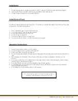
6.  To remove used fluid from the differential turn the Hose Selector Valve to INTAKE position and the Pump 

Selector Valve to WASTE fluid position.

7.  Once used fluid is removed, turn Pump Selector Valve to OFF position.
8.  To refill differential with clean fluid turn Hose Selector Valve to EXHAUST position and Pump Selector 

Valve to CLEAN fluid position.

9.  Once refilled turn Pump Selector Valve to OFF position.

Initial Setup 

1.  Connect appropriate air nipple to air inlet port. (Use 1” wrench to hold hex when installing air nipple)
2.  Install new fluid tank on side of cabinet using supplied screws and spacers.
3.  Connect hose to the bottom of the clean fluid tank

Initial System Flush

The Diff-Vac 1000 is tested with light weight oil.  To remove any residual light weight oil remaining in the outlet 
hose perform the following procedure:

1.  Pour 1qt (946ml) gear oil into Clean Fluid Tank.

2.  Turn Hose Selector Valve to Exhaust position.

3.  Direct hose outlet waste fluid reservoir.

4.  Connect shop air inlet port.

5.  Turn Pump Selector Valve to Clean Fluid.

6.  Turn Pump Selector Valve to off when residual oil is purged.

4

TIP – To stop the flow instantly turn the hose selector valve to 

off position.  Residual pressure will remain in the hose.

Содержание Diff-Vac 1000

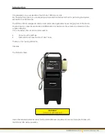
Страница 1: ...1324 Blundell Rd Mississauga ON Tel 905 615 8620 Fax 905 615 9745 www motorvac com USER MANUAL Diff Vac 1000 Differential Fluid Service System Part No 500 9025...

Страница 2: ...ations by exchanging most of the fluid in engine oil pans manual transmissions and differentials Connections to the vehicle are achieved with the supplied adapters Once connected the unit can be safel...

Страница 3: ...nfo motorvac com www motorvac com Table of Contents Page Warnings System Features and Functions Controls Initial Setup Initial System Flush Operating Instructions Troubleshooting Parts 1 2 3 4 4 4 5 5...

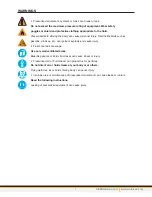
Страница 4: ...lode and cause injury Fluids can leak or escape Use only well ventilated areas Breathing vapors or fluids from leaks can cause illness or injury Pressurized air or fluid stream can propel dust or part...

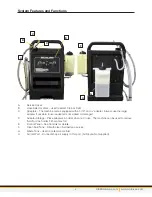
Страница 5: ...kinked or damaged D Adapter Storage Place adapters in holder when not in use The machine can be used to remove fluid from the holder if it becomes full E Control Panel See Controls for details F Clea...

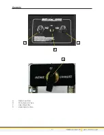
Страница 6: ...Controls A Waste Fluid Filter B Pump Selector Valve C Clean Fluid Filter D Hose Selector Valve info motorvac com www motorvac com 3 A B C D...

Страница 7: ...position and Pump Selector Valve to CLEAN fluid position 9 Once refilled turn Pump Selector Valve to OFF position Initial Setup 1 Connect appropriate air nipple to air inlet port Use 1 wrench to hold...

Страница 8: ...r adapter whenever possible Clean screen filters on control panel Parts Please refer to the part numbers below when ordering parts for this unit Part Description 050 2430 Pump Air Operated 98820975 Ba...

Страница 9: ...1324 Blundell Rd Mississauga ON Tel 905 615 8620 Fax 905 615 9745 www motorvac com ZIM13 00872...

Отзывы: