


Preparing the Board
http://www.motorola.com/computer/literature
1-5
1
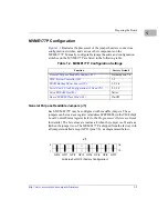
MVME177P Configuration
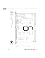
illustrates the placement of the jumper headers, connectors,
configuration switches, and various other components on the
MVME177P. Manually configurable jumper headers and configuration
switches on the MVME177P are listed in the following table.
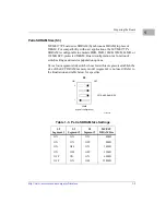
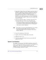
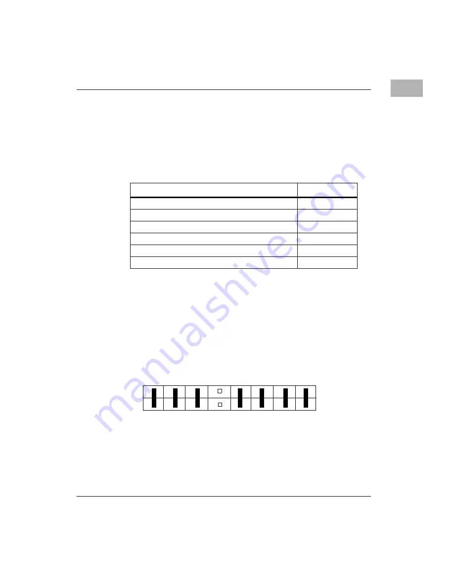
General Purpose Readable Jumpers (J1)
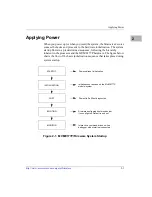
Each MVME177P may be configured with readable jumpers. These
jumpers can be read as a register (at address $FFF40088) in the VMEchip2
Local Control/Status register (refer to the Programmer’s Reference Guide
for details). The bit values are read as a 1 when the jumper is off, and as a
0 when the jumper is on. The MVME177P is shipped from the factory with
all jumpers installed except GPI3 (pins 7-8), as diagrammed below.
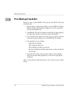
Table 1-2. MVME177P Configuration Settings
Function
Factory Default
General Purpose Readable Jumpers (J1)
No jumper on 7-8
1-2
1-3, 2-4
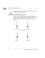
Serial Port 4 Clock Configuration (J10 and J11)
2-3, 2-3
Varies
On-Off
J1
2
1
16
15
GPI0
GPI1
GPI2
GPI3
GPI4
GPI5
GPI6
GPI7
All Zeros but GPI3 (Factory Configuration)
Содержание MVME177P
Страница 1: ...MVME177P Single Board Computer Installation and Use V177PA IH1 Edition of October 2000 ...
Страница 10: ...x ...
Страница 12: ...xii ...
Страница 14: ...xiv ...
Страница 34: ...1 16 Computer Group Literature Center Web Site Hardware Preparation and Installation 1 ...
Страница 48: ...2 14 Computer Group Literature Center Web Site Startup and Operation 2 ...
Страница 92: ...C 2 Computer Group Literature Center Web Site Network Controller Data C ...
Страница 98: ...D 6 Computer Group Literature Center Web Site Disk Tape Controller Data D ...
Страница 108: ...Index IN 6 Computer Group Literature Center Web Site I N D E X ...


