Theory of Operation
2 - 6
68P02963C70-O
data is sent for further processing to the Digital Signal Processor (DSP) (part of
RedCap2) over the Synchronous Serial Interface (SSI) data links.
The DSP performs: the demodulation, Forward Error Correction (FEC) and other
correction algorithms for overcoming channel errors, and the GCAP decoder pro-
cedure for digital speech data decompression.
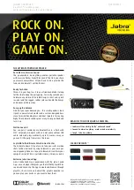
Transmitter Path
When the radio is transmitting (see Figure 3), the microphone audio is sent to the
GCAP (CODEC). The CODEC performs analog-to-digital conversion and the
digital signal is routed to the DSP. The DSP performs coding, Error Correction and
modulation. From the DSP, the signal is sent to the WPIC+.
Figure 3 Transmit Path Block Diagram
In the WPIC+ data is converted into analog signal. This signal is also filtered.
From the WPIC+, the data is injected to the LNODCT. In the LNODCT the data
is mixed with RF signal.
From the differential output of the LNODCT the modulated RF signal is injected
to the Balun-Filter, that transforms the differential input into single output, and
then it is routed to the antenna via the Antenna Switch.
The feedback signal is used for power control.
Harmonic
Filter
Antenna
Switch
-0.8dB
-1dB
4dB
-8dB
-3.5dB
36 - 39dB
RF PA
Balun-Filter
LNODCT
WPIC+
REDCAP2
GCAP
Isolator
Attenuator
Attenuator
Power at Antenna:30dBm ± 2dB
Содержание MTH500
Страница 10: ...Contents x 68P02963C70 O THIS PAGE INTENTIONALLY LEFT BLANK ...
Страница 14: ...Foreword xiv 68P02963C70 O THIS PAGE INTENTIONALLY LEFT BLANK ...
Страница 18: ...Overview 1 4 68P02963C70 O THIS PAGE INTENTIONALLY LEFT BLANK ...
Страница 50: ...Theory of Operation 2 32 68P02963C70 O THIS PAGE INTENTIONALLY LEFT BLANK ...
Страница 76: ...Troubleshooting 3 26 68P02963C70 O Offset VCO Test ...
Страница 78: ...Troubleshooting 3 28 68P02963C70 O This page left blank intentionally ...
Страница 82: ...Programming the Radio 4 4 68P02963C70 O This page left blank intentionally ...
Страница 100: ...Maintenance 5 18 68P02963C70 O Figure 23 Exploded View 1 2 3 4 5 7 6 X6 8 ...
Страница 101: ...Maintenance 68P02963C70 O 5 19 Figure 24 Exploded View of Chassis Assembly 9 12 13 10 11 14 ...
Страница 102: ...Maintenance 5 20 68P02963C70 O ...
Страница 103: ...MTH500 Detailed Service Manual COMPONENT BOARD LAYOUTS 68P02963C70 O 6 1 Component Board Layouts ...
Страница 104: ...MTH500 Detailed Service Manual COMPONENT BOARD LAYOUTS 6 2 68P02963C70 O This page intentionally left blank ...
Страница 109: ...MTH500 Detailed Service Manual Schematic Diagrams and Parts Lists 68P02963C70 O 6 7 Schematic Diagrams and Parts Lists ...
Страница 134: ...SCHEMATIC DIAGRAMS MTH500 Flex CD 6 32 68P02963C70 O This page left blank intentionally ...
Страница 140: ...Replacement Parts and Kits 6 68P02963C70 O ...
Страница 141: ...Replacement Parts and Kits 68P02963C70 O 7 ...
Страница 142: ...Replacement Parts and Kits 8 68P02963C70 O ...
Страница 144: ...Test Equipment Service Aids Tools A2 2 68P02963C70 O THIS PAGE INTENTIONALLY LEFT BLANK ...