6809510A66-O
October 12, 2006
27
Level 1 and 2 Service Manual
Disassembly
3.
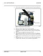
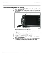
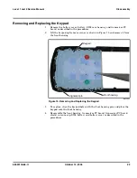
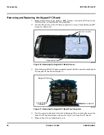
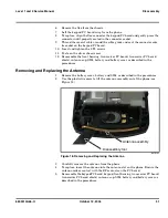
Lift the camera assembly away from the transceiver PC board (see Figure 13).
4.
Remove the rubber grommet from the camera assembly.
5.
To replace, place the rubber camera assembly grommet onto the camera
assembly. Ensure the flat side of the grommet is facing away from the flex
connector.
6.
Align the camera assembly to the transceiver PC board.
7.
Slide the camera assembly into its slot on the transceiver PC board.Ensure
that the flat side of the camera grommet lines up with the outer edge of the PC
board.
8.
Carefully press the camera flex connector into its socket on the transceiver PC
board.
9.
Reassemble the transceiver PC board, transceiver PC board shield, antenna
cap, SIM, battery and battery cover as described in the procedures.
061504o
Figure 13. Removing the Camera Assembly
C
a
mer
a
ass
em
b
ly
Di
sass
em
b
ly tool
Содержание MOTOSLVR L72
Страница 4: ...4 October 12 2006 6809510A66 O Contents MOTOSLVR L9 L72 ...
Страница 49: ......

