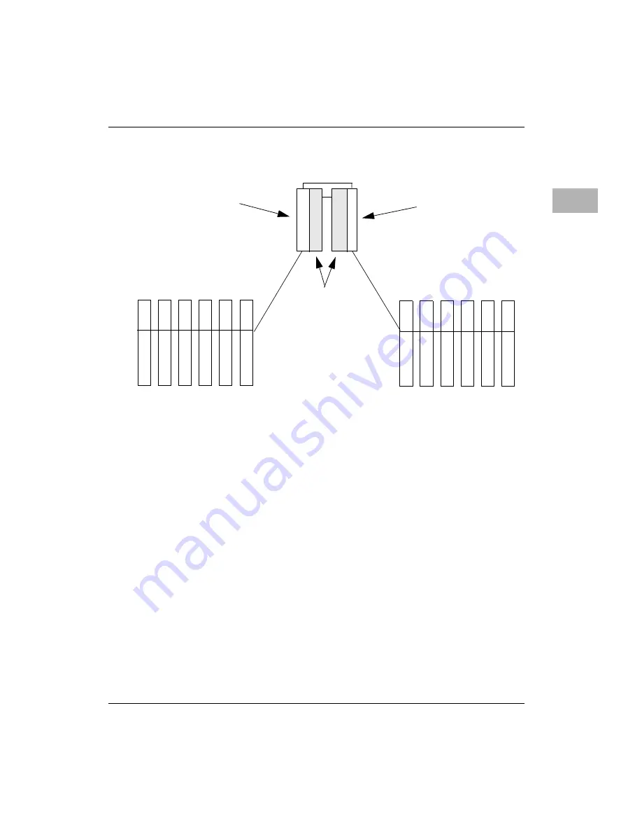
Block Diagram
http://www.motorola.com/computer/literature
3-7
3
Figure 3-2. Active/Passive System
Domain Ownership
In High Availability system implementations, the PCI-to-PCI bridge is not
available until the Domain ownership is established. The PCI-to-PCI
bridge will not connect to the CPCI bus until directed by software. This
default is the result of the architecture, in which the Domains may already
be actively under the control of a second CPU board. In this case, live
insertion of a MCP750HA must not disrupt the active CPCI bus.
The bus ownership is automatically established by the hot swap control
circuitry in non-high availability systems. The backplane must leave the
control lines J3-A15, J3-A16, J3-A17, and J3-A18 as no connects in non-
high availability implementations. Pull-up resistors located on the
MCP750HA will then allow for normal PCI-to-PCI Bridge operation.
I/O
S
L
O
T
I/O
S
L
O
T
I/O
S
L
O
T
I/O
S
L
O
T
I/O
S
L
O
T
I/O
S
L
O
T
I/O
S
L
O
T
I/O
S
L
O
T
I/O
S
L
O
T
I/O
S
L
O
T
I/O
S
L
O
T
I/O
S
L
O
T
C
P
U
C
P
U
H
S
C
H
S
C
I/O Domain A
I/O Domain B
A B
A
B
Active CPU
Active HSC
Passive
CPU/HSC


