I
ECX-APL0 Series User’s Manual
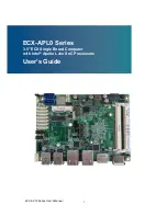
ECX-APL0 Series
3.5" ECX Single Board Computer with Intel
®
Apollo Lake SoC Processors
User’s Guide
Страница 1: ...I ECX APL0 Series User s Manual ECX APL0 Series 3 5 ECX Single Board Computer with Intel Apollo Lake SoC Processors User s Guide...
Страница 2: ...tent rights of Quanmax nor the rights of others Quanmax is a registered trademark of Quanmax All trademarks registered trademarks and trade names used in this user s guide are the property of their re...
Страница 3: ...ining Your Computer 13 Chapter 1 Introduction 16 Overview 16 Product Specifications 17 System Block Diagram 18 Mechanical Dimensions 19 Chapter 2 Hardware Settings 20 Overview 20 Jumper Settings and P...
Страница 4: ...Content 4 ECX APL0 Series User s Manual Chapter 5 Driver Installation 59 Appendix A DIO Digital I O Sample Code 60 Appendix B WatchDog Timer Sample Code 64...
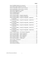
Страница 5: ...Figure 2 Mechanical Dimensions 19 Figure 3 Jumper Connector 20 Figure 4 Jumper and Connector Locations 21 Figure 5 Rear Panel IO 33 Figure 6 Align the SO DIMM Memory Module with the onboard socket 36...
Страница 6: ...Header 25 Table 17 CN7 SIM Interface Wafer for MPCIE1 and M2 KEY B 26 Table 18 CN11 Audio Input Output Pin Header 26 Table 19 CN12 Left Channel 3W Audio AMP Output Wafer 26 Table 20 CN14 Digital Input...
Страница 7: ...Menu Super IO Configuration Serial Port 2 Configuration 43 Table 47 Advanced Menu Super IO Configuration Serial Port 3 Configuration 44 Table 48 Advanced Menu Super IO Configuration Serial Port 4 Conf...
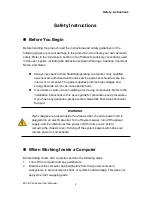
Страница 8: ...dily harm Use extreme caution when installing or removing components Refer to the installation instructions in this user s guide for precautions and procedures If you have any questions please contact...
Страница 9: ...pins Also before connecting a cable make sure both connectors are correctly oriented and aligned CAUTION Do not attempt to service the system yourself except as explained in this user s guide Follow...
Страница 10: ...sensitive components at an ESD workstation If possible use antistatic floor pads and workbench pads Handle components and boards with care Don t touch the components or contacts on a board Hold a boa...
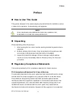
Страница 11: ...mage If there is damage notify Quanmax customer service immediately Refer to Warranty Policy for the return procedure Regulatory Compliance Statements This section provides the FCC compliance statemen...
Страница 12: ...accident acts of God or other causes beyond the control of Quanmax or the manufacturer Neglect misuse and abuse shall include any installation operation or maintenance of the product other than in acc...
Страница 13: ...ct furnished hereunder Quanmax s liability shall in no event exceed the purchase price of the product purchased hereunder The foregoing limitation of liability shall be equally applicable to any servi...
Страница 14: ...orm at reduced efficiency Power Protection The greatest threats to a system s supply of power are power loss power spikes and power surges caused by electrical storms which interrupt system operation...
Страница 15: ...e power to the system for a limited amount of time depending on the UPS system UPS systems range in price from a few hundred dollars to several thousand dollars with the more expensive unit s allowing...
Страница 16: ...y integrated M 2 expansion socket for Wi Fi Bluetooth satellite navigation NFC digital radio WiGig WWAN and SSDs Thus it allows developers to build more compact or thinner embedded devices Checklist O...
Страница 17: ...case of eliminating M 2 SATA support 1x Micro SD Cage on front 1x mPCIe Socket full size 1x M 2 Key B mixed with USB2 0 SATA type 22x42 1x SIM card wafer switchable between mPCIe and M 2 Power Connect...
Страница 18: ...Chapter 1 18 ECX APL0 Series User s Manual System Block Diagram Figure 1 Block Diagram...
Страница 19: ...Chapter 1 19 ECX APL0 Series User s Manual Mechanical Dimensions Figure 2 Mechanical Dimensions...
Страница 20: ...ion Figure 3 Jumper Connector For a three pin jumper see Figure 3 the jumper setting is designated 1 2 when the jumper connects pins 1 and 2 The jumper setting is designated 2 3 when pins 2 and 3 are...
Страница 21: ...Chapter 2 21 ECX APL0 Series User s Manual Jumper Settings and Pin Definitions For jumper and connector locations please refer to the diagrams below Figure 4 Jumper and Connector Locations...
Страница 22: ...eset Selection JP9 USB Power Selection JP10 ME F W Selection Table 3 JP1 SIM CARD SELECTION 1 2 Jumper Status 1 2 Open M 2 KEY B 1 2 Short MPCIE Default DIP 2P 1R MALE Pitch 2 54mm Pinrex 210 91 02GB0...
Страница 23: ...2 Pin Descriptiom 1 LED 2 LED DIP 2P 1R MALE Pitch 2 54mm Pinrex 210 91 02GB01 Table 9 JP8 RTC Reset Selection 1 2 Jumper Status 1 2 Open Normal Operation 1 2 Short Clear CMOS DIP 2P 1R MALE Pitch 2...
Страница 24: ...igital Input Output Wafer CN16 Right Channel 3W Audio AMP Output Wafer CN17 COM1 RS 232 422 485 Port Wafer CN18 COM2 RS 232 422 485 Port Wafer CN19 RS 232 Port 5 Wafer CN20 RS 232 Port 3 Wafer CN21 RS...
Страница 25: ...5V WAFER SMD MALE 4P 1R 180D P 2 0mm Tin Plated White Insulator PINREX 721 93 04TWE9 Table 15 CN3 Micro SD Card Cage Pin Signal Name 1 DAT2 2 CD DAT3 3 CMD 4 VDD 5 CLK 6 GND 7 DAT0 8 DAT1 SMT 8P Micr...
Страница 26: ...n_R 3 MIC In_JD 4 GND 5 Line In_L 6 Line In_R 7 Line In_JD 8 GND 9 Line Out_L 10 Line Out_R 11 Line Out_JD 12 GND SMD 12P 2R 180D Pitch 2 54mm Gold Flash NY9T Green Insulator PINREX 212 92 06GBE1 Tabl...
Страница 27: ...RTS N A N A N A 5 TXD RX N A RX 6 CTS N A N A N A 7 DTR RX N A RX 8 RI N A N A N A 9 GND GND GND GND 10 5V 5V 5V 5V SMD 10P 1R 180D MALE P 1 25mm Tin Plated NY46 White Insulator Pinrex 712 73 10TWB0 T...
Страница 28: ...7MTR 1R BL_ADJ can be setting in BIOS setup Backlight Power can be selected by JP3 BL_EN can be selected by JP2 Table 26 LVDS1 18 24 bit 1 2 channel LVDS Panel Connector Pin Signal Name Pin Signal Nam...
Страница 29: ...et Button 4 NC 5 HDD LED 6 Internal Speaker 7 HDD LED 8 Speaker SMD 8P 2R MALE STRAIGHT TYPE Pitch 2 54mm NY 6T YIMTEX 3362 04SANGR Note Internal Buzzer is enabled when Pin6 8 is shorted Table 29 FP2...
Страница 30: ...Ground Reserved 19 20 W_Disable Ground 21 22 PERST PERn0 23 24 3 3VSB PERp0 25 26 Ground Ground 27 28 1 5V Ground 29 30 SMB_CLK PETn0 31 32 SMB_DATA PETp0 33 34 Ground Ground 35 36 USB_D Ground 37 38...
Страница 31: ...31 32 UIM CLK GND 33 34 UIM DATA NC 35 36 UIM PWR NC 37 38 DEVSLP GND 39 40 GPIO0 PETn0 SATAB 41 42 GPIO1 PETp0 SATAB 43 44 GPIO2 GND 45 46 GPIO3 PERn0 SATAA 47 48 GPIO4 PERp0 SATAA 49 50 PERST GND 5...
Страница 32: ...nector Pin Signal Name 1 GND 2 TX 3 TX 4 GND 5 RX 6 RX 7 GND SATA 7P 180D CONN BLUE double row pin parallel positioning peg WIN WIN WATM 07ABN4A2B8UW4 Table 33 CN26 USB2 0 Port Wafer Option Pin Signal...
Страница 33: ...nnector CN5 USB3 0 Port 3 4 Type A Connector CN13 DP Connector CN15 HDMI Connector Table 35 CN9 GbE LAN1 RJ 45 Connector Pin Signal Name Pin Signal Name 1 TX1 5 TX3 2 TX1 6 TX2 3 TX2 7 TX4 4 TX3 8 TX4...
Страница 34: ...Port 2 3 Type A Connector Pin Signal Name Pin Signal Name 1 USBA_VCC 10 USBB_VCC 2 USBA_D 11 USBB_D 3 USBA_D 12 USBB_D 4 GND 13 GND 5 USBA_RX 14 USBB_RX 6 USBA_RX 15 USBB_RX 7 GND 16 GND 8 USBA_TX 17...
Страница 35: ...DS Data2 4 TMDS Data1 5 Ground 6 TMDS Data1 7 TMDS Data0 8 Ground 9 TMDS Data0 10 TMDS Clock 11 Ground 12 TMDS Clock 13 Reserved 14 Reserved 15 DDC_CLK 16 DDC_DATA 17 Ground 18 5 V Power 19 Hot Plug D...
Страница 36: ...amaging the SO DIMM ground yourself by touching a grounded metal surface or use a ground strap before you touch the SO DIMM 2 Do not touch the connectors of the SO DIMM Dirt or other residue may cause...
Страница 37: ...he module Figure 7 Press down on the SO DIMM Memory Module to lock it in place Removing a DIMM To remove the SO DIMM use your fingers or a small screwdriver to carefully push away the tabs that secure...
Страница 38: ...please contact Quanmax AMI s ROM BIOS provides a built in Setup program which allows the user to modify the basic system configuration and hardware parameters The modified data will be stored in a bat...
Страница 39: ...BIOS Main Menu BIOS SETUP UTILITY M a i n A d v a n c e d P o w e r B o o t S e c u r i t y S a v e E x i t Product Information Select Screen Select Item Enter Select Change Opt F1 General Help F2 Pr...
Страница 40: ...d Defaults F4 Save Exit ESC Exit Onboard LAN2 Controller Enabled Audio Controller Enabled M 2 Device Type mSATA Display Configuration Super IO Configuration CPU Chipset Configuration SATA Configuratio...
Страница 41: ...Defaults F4 Save Exit ESC Exit Primary Display UMA Frame Buffer Size IGD 256MB DVMT Pre Allocated 64M DVMT Total Gfx Mem 256M AMI Graphic Output Protocol Policy Active LVDS Disabled Version 2 18 1263...
Страница 42: ...guration Serial Port 1 Configuration BIOS SETUP UTILITY M a i n A d v a n c e d P o w e r B o o t S e c u r i t y S a v e E x i t Serial Port 1 Configuration Select Screen Select Item Enter Select Cha...
Страница 43: ...ults F4 Save Exit ESC Exit Serial Port Enabled Device Settings IO 2F8h IRQ 10 Change Settings Auto Serial Port 2 Type RS232 Version 2 18 1263 Copyright C 2017 American Megatrends Inc Serial Port Optio...
Страница 44: ...lect Item Enter Select Change Opt F1 General Help F2 Previous Values F3 Optimized Defaults F4 Save Exit ESC Exit Serial Port Enabled Device Settings IO 3E8h IRQ 7 Change Settings Auto Version 2 18 126...
Страница 45: ...lect Item Enter Select Change Opt F1 General Help F2 Previous Values F3 Optimized Defaults F4 Save Exit ESC Exit Serial Port Enabled Device Settings IO 2E8h IRQ 7 Change Settings Auto Version 2 18 126...
Страница 46: ...lect Item Enter Select Change Opt F1 General Help F2 Previous Values F3 Optimized Defaults F4 Save Exit ESC Exit Serial Port Enabled Device Settings IO 2F0h IRQ 7 Change Settings Auto Version 2 18 126...
Страница 47: ...lect Item Enter Select Change Opt F1 General Help F2 Previous Values F3 Optimized Defaults F4 Save Exit ESC Exit Serial Port Enabled Device Settings IO 2E0h IRQ 7 Change Settings Auto Version 2 18 126...
Страница 48: ...t F1 General Help F2 Previous Values F3 Optimized Defaults F4 Save Exit ESC Exit EIST Enabled Turbo Mode Enabled Active Processor Cores Disabled Intel Virtualization Technology Enabled VT d Disabled V...
Страница 49: ...F1 General Help F2 Previous Values F3 Optimized Defaults F4 Save Exit ESC Exit SATA Controller Enabled SATA Mode Selection AHCI Serial ATA Port 1 Not Installed Port 1 Enabled mSATA Port 1 Not Install...
Страница 50: ...tem Enter Select Change Opt F1 General Help F2 Previous Values F3 Optimized Defaults F4 Save Exit ESC Exit USB Devices 1 Keyboard Legacy USB Support Enabled XHCI hand off Enabled USB Mass Storage Driv...
Страница 51: ..._0 Value 1 DIO_1 Value 1 DIO_2 Value 1 DIO_3 Value 1 DIO_4 Value 1 DIO_5 Value 1 DIO_6 Value 1 DIO_7 Value 1 Version 2 18 1263 Copyright C 2017 American Megatrends Inc User Configuration Options Enabl...
Страница 52: ...t y S a v e E x i t Network Stack Disabled Select Screen Select Item Enter Select Change Opt F1 General Help F2 Previous Values F3 Optimized Defaults F4 Save Exit ESC Exit Version 2 18 1263 Copyright...
Страница 53: ...lect Item Enter Select Change Opt F1 General Help F2 Previous Values F3 Optimized Defaults F4 Save Exit ESC Exit Smart FAN Configuration CPU Temperature 39 C System Temperature 39 C CPU Fan Speed N A...
Страница 54: ...Device Disabled Resume By MPCIE1 Device Disabled Resume By M2 Device Disabled Resume By Ring Device Disabled Resume By RTC Alarm Disabled WatchDog Timer Configuration Version 2 18 1263 Copyright C 201...
Страница 55: ...vious Values F3 Optimized Defaults F4 Save Exit ESC Exit Full Screen LOGO Display Disabled Setup Prompt Timeout 1 Bootup NumLock State On CSM Support Enabled Boot Option Filter UEFI only Boot Option P...
Страница 56: ...entering Setup If ONLY the User s password is set then this is a power on password and must be entered to boot or enter Setup In Setup the User will have Administrator rights The password length must...
Страница 57: ...ned off When you select this option a confirmation window appears Select Yes to save changes and exit Discard Changes and Exit Exit system setup without saving any changes Select this option only if y...
Страница 58: ...to save the changes that you made to the Setup program If you made changes to fields other than system date system time and password the BIOS asks for a confirmation before exiting Discard Changes Di...
Страница 59: ...nnected the appropriate power source power it up using the power supply and install the desired operating system You can download the drivers for the ECX APL0 Series from the Quanmax website at www qu...
Страница 60: ...able DIO_1 0xD0C50500 bit0 bit1 bit8 bit9 DIO_2 0xD0C50508 bit0 bit1 bit8 bit9 DIO_3 0xD0C50510 bit0 bit1 bit8 bit9 DIO_4 0xD0C50518 bit0 bit1 bit8 bit9 DIO_5 0xD0C50520 bit0 bit1 bit8 bit9 DIO_6 0xD0...
Страница 61: ...mode n for i 0 i 8 i RetVal read_mem_dword MEM_BASE_ADDRESS addr_offset i RetVal RetVal 0xFFFFFCFF gGpioLvValue RetVal 0x100 Set TX Disable Bit8 write_mem_dword MEM_BASE_ADDRESS addr_offset i gGpioLvV...
Страница 62: ...al 0x1 write_mem_dword MEM_BASE_ADDRESS addr_offset i gGpioLvValue printf Read DIO_1 8 value n for i 0 i 8 i RetVal read_mem_dword MEM_BASE_ADDRESS addr_offset i gGpioLvValue RetVal 0x1 printf DIO_ d...
Страница 63: ...Appendix A 63 ECX APL0 Series User s Manual gGpioLvValue RetVal 0x1 printf DIO_ d d n i 1 gGpioLvValue 0 into_RL_mode return 0...
Страница 64: ...455 Ti Ding Blvd Sec 2 Neihu District Taipei Taiwan 114 Phone 886 2 2799 2789 ECX APL0 DOS Watchdog sample program Please compile with Turbo C 3 0 to utilized the program include stdio h define SIO_C...
Страница 65: ...etLDN 0x08 Enable WDT outp SIO_CONFIG_INDEX 0x30 outp SIO_CONFIG_DATA 0x01 Set Timer unit 0xF0 bit3 0 1sec 1 60 sec of watchdog timer by setting this bit outp SIO_CONFIG_INDEX 0xF0 value inp SIO_CONFI...