9
Hardware Installation
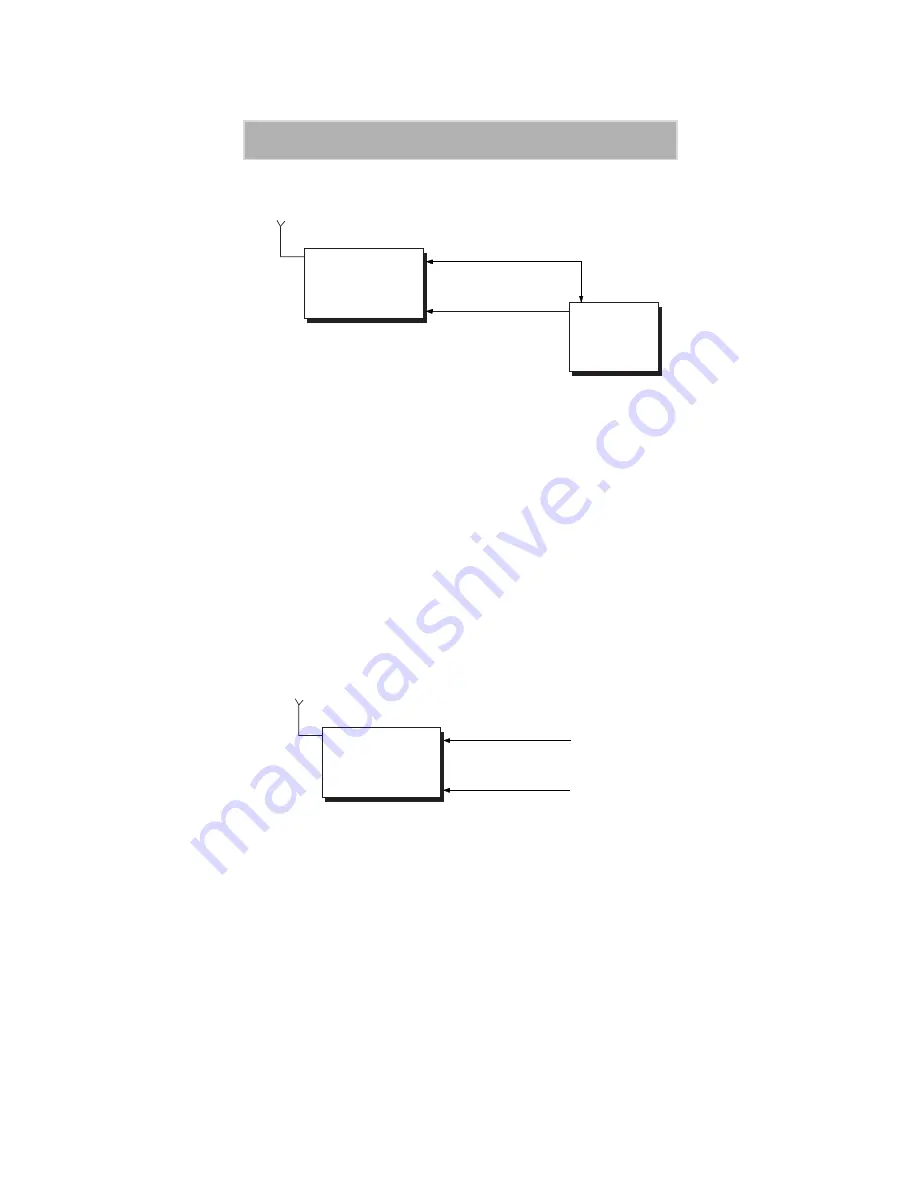
Figure 5. Switched Power Connection
Perform the following steps to install the iM1000 modem in the vehicle.
1. Prepare a routing plan for the ignition cable after determining where
the iM1000 is to be mounted.
2. Connect the free end of the ignition cable to the vehicle ignition
switch, and the other end (with the plug) to the iM1000 ignition
connector.
Continuous Power Connection
A power on plug is permanently plugged into the ignition connector. When
the power is supplied to the iM1000 DC Power connector, the modem turns
ON.
Figure 6. Continuous Power Connection
Data Cable Installation
Connect one side of the 9-pin cable (FKN4369A) to the iM1000
communication connector and the other side to the DTE. Since the iM1000
is a modem, it can be connected only to the DTE equipment, using a 9-pin
to 9-pin cable.
Car
Switch
Ignition Cable
FKN4868A
PWR
IGN
iM1000
Pwr Cable FKN4878A
Vehicle
Battery
Antenna
Power On Plug
FLN9400A
PWR
IGN
iM1000
FKN4878A
Antenna
Power Source


