background image

PRECAUCIONES DE OPERACIÓN

ADVERTENCIA: PARA EVITAR RIESGOS DE 
INCENDIOS O DESCARGA ELÉCTRICA, NO 
EXPONGA ESTE EQUIPO A LA LLUVIA O LA 

HUMEDAD.

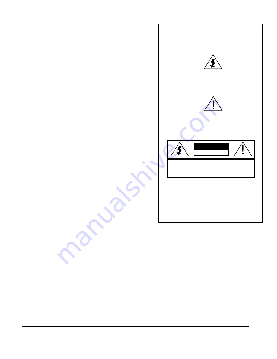
El símbolo del rayo con cabeza de flecha, dentro de un 

triángulo equilátero, está diseñado para alertar al usuario la 
presencia de "voltaje peligroso" sin aislamiento dentro del 
perímetro del producto que puede tener la magnitud suficiente 

para ser un riesgo de descarga eléctrica para las personas.

El signo de exclamación dentro de un triángulo 
equilátero está diseñado para alertar al usuario la 

presencia de importantes instrucciones de 
funcionamiento y mantenimiento (servicio) en la 
literatura que acompaña al producto.

ATENCIÓN 

Esta unidad comercial está diseñada para decodificar seña-

les de televisión DigiCipher

® 

II para uso comercial. La 

posesión de este dispositivo no permite ni autoriza al dueño 
a recibir señales de televisión DigiCipher II. Comuníquese 

con los proveedores de programa para obtener las autoriza-
ciones correspondientes.


MOTOROLA y el logotipo de la M estilizada son marcas 
comerciales o marcas comerciales registradas de Marcas 

Participantes de Motorola LLC. Todas las demás marcas 
comerciales son propiedad de sus respectivos dueños.
Dolby Digital es una marca comercial registrada de Dolby 
Laboratories. Dolby Digital está fabricado bajo la licencia 
de Dolby Laboratories.
© 2010 Motorola Mobility, Inc. Todos los derechos 
reservados.

PRECAUCIÓN

PRECAUCIÓN: 

PARA REDUCIR EL RIESGO DE DESCARGA 

ELÉCTRICA, NO RETIRE LA CUBIERTA (O LA TAPA). EN EL 
INTERIOR NO H AY PIEZAS QUE SEAN PARA USO DEL USUARIO.
SOLICITE ASISTENCIA TÉCNICA AL PERSONAL DE SERVICIO 
CALIFICADO.

RIESGO DE DESCARGA 
ELÉCTRICA. NO ABRIR.

ADVERTENCIA

La modificación no autorizada de cualquier unidad, y la venta y el uso 
del mismo está prohibida por ley. Cualquier modificación o alteración 
de este producto o cualquier recepción no autorizada de programación 
de televisión puede someter al usuario y al vendedor, y a la parte que 
modifica la unidad a multas, prisión y daños civiles.

NOTA: Este equipo se ha probado y se ha demostrado que cumple con 
los límites para un dispositivo digital clase A, según la parte 15 de las 
normas de la FCC. Estos límites están diseñados para ofrecer protección 
adecuada contra interferencia dañina cuando el equipo se utiliza en un 
entorno comercial. Este equipo genera, usa y puede irradiar energía de 
radiofrecuencia y, si no se instala y usa de acuerdo con el manual de 
instrucciones, puede causar interferencia dañina a las comunicaciones 
por radio. Es posible que el funcionamiento de este equipo en un área 
residencial cause interferencia dañina, en cuyo caso el usuario deberá 
corregir la interferencia y asumir el costo correspondiente. Este aparato 
digital no supera los límites de la clase A de emisiones de ruido de radio 
del aparato digital establecido en las Normas de interferencia de radio 
del Departamento canadiense de comunicaciones.

Reparación y asistencia

Para recibir ayuda sobre devolución o reparación, consulte “Product 
Support” en la página 69.

Nota para el instalador del sistema CATV

Este recordatorio es para que el instalador del sistema CATV 
considere el Artículo 820-40 del Código eléctrico nacional (NEC) que 
entrega pautas para una correcta conexión a tierra y, en especial, 
especifica que la conexión a tierra del cable debe conectarse al sistema 
de conexión a tierra del edificio, lo más cerca posible del punto de 
entrada del cable.

Advertencia

Para evitar descargas eléctricas, no use el enchufe eléctrico de la unidad 
(polarizado) con un cable de extensión, receptáculo u otra salida a 
menos que las aspas queden completamente insertadas para evitar la 
exposición de las aspas. El dispositivo de desconexión de la red de 
suministro es el enchufe del aparato y debe ser de fácil acceso y estar en 
funcionamiento.

La batería de litio no se reemplaza en la instalación para mantener la 
vida útil del producto. 

General Instrument Corporation comercializa como 


Motorola Mobility, Inc.


6450 Sequence Dr. 


San Diego, CA 92121

N°. DE DOCUMENTO: 578523-001 REV B, 12/9/10

Содержание DSR-6100

Страница 1: ...Document No 578523 001 Motorola DSR 6100 Commercial Integrated Receiver Transcoder Operator Guide DSR 6100 ...

Страница 2: ...fying the unit to fines imprisonment and civil damages NOTE This equipment has been tested and found to comply with the limits for a Class A digital device pursuant to Part 15 of the FCC Rules These limits are designed to provide reasonable protection against harmful interference when the equipment is operated in a commercial environment This equipment generates uses and can radiate radio frequenc...

Страница 3: ... where they exit from the apparatus Use only attachments and accessories specified by the manufacturer Unplug this apparatus during lightning storms or when unused for long periods of time Refer all servicing to qualified service personnel Servicing is required when the apparatus has been damaged in any way such as when the power supply cord or plug is damaged liquid has been spilled or objects ha...

Страница 4: ...uario y al vendedor y a la parte que modifica la unidad a multas prisión y daños civiles NOTA Este equipo se ha probado y se ha demostrado que cumple con los límites para un dispositivo digital clase A según la parte 15 de las normas de la FCC Estos límites están diseñados para ofrecer protección adecuada contra interferencia dañina cuando el equipo se utiliza en un entorno comercial Este equipo g...

Страница 5: ...plo cuando el cable de alimentación o enchufe está dañado se ha derramado líquido o el aparato ha sido golpeado por otros objetos cuando se ha expuesto a lluvia o humedad no funciona normalmente o se ha caído Proteja el cable de alimentación para evitar pisarlo o que quede apretado especialmente en los enchufes y tomas de corriente y revise el punto de salida del aparato Use exclusivamente los acc...

Страница 6: ......

Страница 7: ...tion 13 Chapter 3 Operating the DSR 6100 15 Using the Front Panel 16 Navigating the Menus 17 How to Use the Menus 18 About Menu 18 Main Menu 18 Overview of The LCD Panel Menu Tree 19 Installation Menus 22 Manual Tune Menu 22 ASI Usage 23 Input Field 23 GigE Usage 23 Input Field 23 GigE Input IP Addr Field 24 RF Usage 24 Input Field 25 Mode Field 25 Xpndr Field 26 LFreq Field 26 Modulation Menu 27 ...

Страница 8: ...e Field 37 Format Field 37 Pid Alias Field 37 Reset Menu 37 Reset Type Field 37 Factory Defaults Option 37 Power Cycle Option 38 Core Menu 38 Contrast Field 38 Video Out Menu 39 525 Field 39 Firmware Menu 39 Boot FPGA High Field 39 Upgrade Field 40 Download Menu 40 File Field 40 Current Field 40 Rcvd Field 40 Total Field 40 Channel Menus 41 Channel Menu 41 VCT Field 41 Channel Field 41 Xpndr Field...

Страница 9: ...50 GigE IP Address Menu 50 GigE Subnet Mask Menu 51 GigE Default Gateway Menu 51 GigE TS Mode Menu 52 TS Mode Field 52 DSMCC Field 52 GigE Xcoder Dest Addr Menu 52 Xcoded Dest Addr Field 52 Port Field 52 GigE PassThru Dest Addr Menu 53 PassThru Dest Addr Field 53 Port Field 53 Status Display Menus 54 Status0 Menu 54 Status1 Menu 55 FrontPanel Field 55 Input Type Field 55 Status2 Menu 56 Source Fie...

Страница 10: ...Mode Field 60 BitRt Field 60 Status9 HD Menu 61 Video Resolution Field 61 BitRt Field 61 Status10 HD Menu 61 Audio Field 61 Format Field 61 Mode Field 61 BitRt Field 62 Status11 Menu 62 Addr field 62 Link field 62 Diagnostic Menus 63 Menus Field 63 Clear Cntrs Field 63 Unit Address Menu 64 TV Pass Card Menu 64 Audio Test Signal Menu 64 L1 R1 and L2 R2 Fields 65 Video Test Signal Menu 65 Pattern Fi...

Страница 11: ...Band Frequency Conversion Tables 71 Chapter 7 Language Abbreviations 73 Chapter 8 Diagnostics 75 Introduction 75 Viewing the Fast Fact Diagnostic Screens 76 Fast Facts 1 77 Fast Facts 2 79 Fast Facts 3 80 Fast Facts 4 Audio 1 and 2 82 Fast Facts 5 10 100 Network 83 Fast Facts 5 Gigabit Ethernet 84 Chapter 9 DSR 6100 Specifications 85 ...

Страница 12: ......

Страница 13: ...information from the satellite operator Key Features Eight RF inputs DC II QPSK and DVB S2 demodulation DigiCipher II security Gig E and ASI Outputs with PID Aliasing One composite video and one diagnostic video output VBI reinsertion for Closed Captioning Two stereo pair audio output DTMF output Three Form C relays with fault alarm indication Uplink controlled retunes Memory configuration is save...

Страница 14: ......

Страница 15: ...2 7 CAUTION DISCONNECT POWERCORD BEFORE SERVICING 100 240 VAC 50 60Hz 1 5A ASYNC SECONDARYAUDIO RELAY 3 PRIMARYAUDIO RELAY CONTACT RATING 1A 30 VDC RELAY 2 ALARM RELAY 1 L L G R R L L G R R NO CM NC G NO CM NC NO CM NC G NO CM NC G Q1 Q1 G O2 O2 D D C C G Q3 Q3 L Band RF Input Ports 1 8 Ethernet Port GigE Port ASI Out Video Out OSD Video Out Relay Alarm Primary Audio Out Secondary Audio Out Power ...

Страница 16: ...UX VIDEO IN SECONDARYAUDIO RELAY 3 PRIMARYAUDIO RELAY 2 ALARM RELAY 1 L L G R R L L G R R NO CM NC G NO CM NC NO CM NC G NO CM NC G L L G R R D D C C G Q Q AUXAUDIOIN ISOC CUE ASYNC 1 CAUTION When connecting any of the eight RF IN ports the RF IN Antenna cable should only be connected while the DSR 6100 is properly grounded and the shield of the coaxial cable should be earthed in accordance with A...

Страница 17: ...arm air output from within the mounting rack Motorola Mobility recommends the use of a fan on top of the rack Circuit Overloading If the DSR 6100 is connected to a power strip rather than a branch circuit s direct connection use special care to ensure that the unit is properly connected Always consider the affect that overloading circuits might have on over current protection and supply wiring To ...

Страница 18: ...mposite video input standard definition Note The DSR 6100 generates time specific ad insertion cue tones The programmer can include these messages in the encoded signal 4 If cue tones are needed and made available connect the differential Cue Tone Cue Tone and Ground terminals on the DSR 6100 to the 600 ohm device receiving the tones Note The DSR 6100 provides an alarm relay that can be used to si...

Страница 19: ...signal e g transponder frequency input port Video and audio output customizations Alarm triggers ASI and Ethernet output customizations To configure the DSR 6100 for remote operation 1 Contact your network administrator for the IP Subnet Mask address unique IP address and default gateway address to assign to this decoder Caution To use DSR 6100 remote operation each DSR 6100 on the subnet must be ...

Страница 20: ...er type http 10 11 23 60 in the address bar and press ENTER 2 When the login dialog box appears as shown below enter the User name and Password and select OK The default user name is ESPN and the password is espn Note Web browser login will not be available until commissioned by the uplink 3 When the Home Page appears as shown below use the sidebar menu to access the decoder s various settings and...

Страница 21: ...when the unit enters an alarm state Authorized Illuminates when the unit is authorized by the service provider Bypass Illuminates when the unit is in the bypass state Signal Illuminates when the unit is locked to a valid carrier Download Illuminates when the unit has successfully received new firmware and is awaiting activation Relay 1 Relay 2 Relay 3 Alarm LCD Screen Authorized Bypass Signal Down...

Страница 22: ...ing for each field Some fields may be changed by the user and others are for display purposes only Fields that can be changed have an arrow indicator just to the left of the field label During left right navigation the cursor skips over the labels that cannot be changed In addition to the menus on the LCD screen the LED indicators show the unit s current status The Signal LED is lit when the unit ...

Страница 23: ...ing the 4 button at the rightmost field label causes the cursor to wrap to the left side of the screen to the menu name Likewise pressing the button when the cursor is at the menu name causes the cursor to wrap to the rightmost field label When the cursor is blinking on a field label top row pressing the ENTER button causes the cursor to move below the label and enter into the field so the setting...

Страница 24: ...n Menu This menu is the top level menu and can be navigated to from any other menu by pressing the ENTER button while the cursor is blinking next to the menu name This menu allows the user to select any one of the five main menu groups Installation menus Channel menus IP menus Status menus and Diagnostic menus The DSR 6100 allows the user to scroll only to menus that are in the same group To scrol...

Страница 25: ...ER button when the cursor is on a menu name causes the cursor to return to the main top level menu The charts on the following pages show the menus organized into five main groups Installation menus Channel selection menus IP menus Status menus and Diagnostic menus ...

Страница 26: ...3 20 ...

Страница 27: ...ostic Menus E Off DIAGNOSTIC MENUS UNIT ADDRESS E ddd ddddd ddddd ddd E Not Inserted TV PASS CARD Status E Off Off AUDIO TEST SIGNAL L1 R1 L2 R2 E Off VIDEO TEST SIGNAL Pattern E Off Off AD INSERTION TEST Cue Tone Relay ...

Страница 28: ... and press the ENTER button The DSR 6100 displays the previously selected sub menu Manual Tune Menu Use this menu to begin to acquire a DigiCipher II system signal by selecting a transponder frequency for one of the eight L Band inputs In addition this menu allows a user to select the ASI input or GigE input as an alternative to RF ports 1 through 8 E Port 1 Xpndr 01 1430 00 MANUAL TUNE Input Mode...

Страница 29: ...appears without any changes To set the port selection press the ENTER button Skip to page 30 to set the remaining installation fields GigE Usage Input Field Use this section to specify the GigE input port The Input field displays the active input Press the4 button until the cursor is at the Input label and press the ENTER button Press the buttons to scroll to GigE In Press ENTER to confirm the sel...

Страница 30: ...e field Skip to page 30 to set the remaining installation fields RF Usage Use this section to select one of the eight RF input ports so that the DSR 6100 can acquire the DigiCipher II system signal and automatically download network data required for operation Because many satellite broadcasters use standard C band transponder center frequencies selecting a transponder number is the default tuning...

Страница 31: ...ency plan type for the satellite signal to which the DSR 6100 is tuned If the application is a North American C band satellite center frequency select the transponder number in the Xpndr field Otherwise set this field to LFreq and also set the new field LFreq as described below The L Freq option can be used for current satellite LNB signals including C band and Ku band Press the4button until the c...

Страница 32: ...k up to the field label LFreq Field This field is not available when Input field is set to either ASI In or GigE In If the Mode field is set to Xpndr this field is set automatically and cannot be edited If the LFreq option in the Mode field is chosen use this field to directly tune the frequency Press the4 button until the cursor is at the LFreq label Then press the ENTER button to move into the f...

Страница 33: ...ceive a DVB S2 modulated carrier the DSR 6100 must be set to DVBS2 mode and the correct Symbol Rate Msps must be entered in the Symbol field In DCII MAN mode the correct Symbol Rate Msps must be entered in the Symbol field Code field and Format field If DCII AUTO is selected the DSR 6100 searches through all available DC II Symbol Code Format combinations to acquire a signal and then remains locke...

Страница 34: ...ives detailed instructions set the Mode field to Manual and set the Sat Satellite field and Polar Polarity field Any mismatch between what is entered into these fields and the Uplink encoder Satellite and Polarity designations for the services will prevent authorization decryption and service output Satellite names and polarity designators for a given service do not necessarily reflect actual sate...

Страница 35: ...ntil the cursor is at the Polar label Press the ENTER button to move into the field and press the buttons to display the options H LHP Horizontal Left Hand Polarity or V RHP Vertical Right Hand Polarity Select a polarity and press ENTER button to confirm the selection and exit the field Port Config Menu Use this menu to configure Low Noise Block LNB power for RF In Port 1 This menus is not availab...

Страница 36: ...dio processing options Press the 4 button until the cursor is at the AudioMix label and press the ENTER button to move into the field Press the buttons to display the options Stereo Stereo output on both left and right channel Surround Enhanced stereo with surround pass through Mono Mono output on left channel Dual Mono Mono output on both left and right channels Caution If Dual Mono is selected a...

Страница 37: ...o display the options Heavy Reduces the louder audio signals and boosts the softer signals using tighter compression thresholds in order to eliminate dramatic fluctuations in the audio signal level and suppress dynamic range of the audio signal Moderate Provides some reduction and amplification of the audio signal but the thresholds are wider apart providing moderate dynamic range of the audio sig...

Страница 38: ...d with the Audio Gain port and is always set to Joint This means both channels are configured jointly using the Left field settings as the control for both audio channels Left and Right Fields Default 00 Note The Right field is not editable The Left field allows adjustment of the output level of the Left and Right audio signals Press the 4 button until the cursor is at the Left label and press the...

Страница 39: ...is set to GigE In Trigger Field Default Auto The Trigger field allows the user to select the trigger condition to activate an alarm on the IRD When the alarm is activated the Alarm LED illuminates and the alarm relay indicates an alarm condition Press the 4 button until the cursor is at the Trigger label and press the ENTER button to move into the field Press the buttons to display the five option...

Страница 40: ...bypassed state if it enters the alarm condition At such time the Aux Video and Audio inputs are routed to the IRD output and the front panel Bypass LED is lit When the DSR 6100 exits the alarm condition the unit switches back to satellite video and audio Press the ENTER button to select the option shown and exit the field Test Field Default Off Note The Test field returns to the default value Off ...

Страница 41: ...ped to a consistent set as described in Tables 3 1 and 3 2 on page 36 This MPEG program corresponds to the program content that is available at the analog video and audio outputs the monitored program Otherwise when PID aliasing is disabled the DSR 6100 outputs an MPEG transport stream at a data rate of 81 Mbps which contains all of the MPEG programs that the DSR 6100 receives from the uplink ASI ...

Страница 42: ...ideo PID 1E00 Audio 1 PID 1020 Audio 2 PID 1021 Program 1 Video PID 1E00 Audio 1 PID 1020 Audio 2 PID 1021 HD Program 2 Video PID 0801 Audio 1 PID 0802 Audio 2 PID 0803 Program 1 Video PID 1E00 Audio 1 PID 1020 Audio 2 PID 1021 HD Program 2 Video PID 0801 Audio 1 PID 0802 Audio 2 PID 0803 Table 3 2 Additional DSR 6100 Output PIDs Component Program 1 PIDs Program 2 PIDs Notes PAT 0x0000 0x0000 N A ...

Страница 43: ...en the Uplink Programmer enforces PID aliasing the PID Alias field displays Lock On and becomes uneditable Reset Menu Press the buttons until the Reset menu appears Use this menu to execute factory defaults and perform power cycle resets Reset Type Field Default No Press the 4 button until the cursor is at the Reset Type label and press the ENTER button to move into the field Press the buttons to ...

Страница 44: ...ttons until the Core menu appears Use this menu to change the front panel LCD contrast Contrast Field Default 18 To adjust the LCD contrast press the 4 button until the cursor is at the Contrast label and press the ENTER button to move into the field Use the arrow buttons to select a value between 0 and 30 with 0 representing the least contrast and 30 the most Adjust the contrast so that the LCD p...

Страница 45: ...irmware Menu Press the buttons until the Firmware menu appears This menu displays the DSR 6100 s firmware release information which is equivalent to the product version number This menu cannot be changed but since the firmware is periodically updated this menu confirms that the update was successful This menu is used most commonly in troubleshooting The High version value shown below is the curren...

Страница 46: ...e during and after a background code download File Field The File field consists of two sub fields The first sub field is editable and selects by index a download file for monitoring The second sub field is non editable and indicates the total number of files that have been downloaded and or are available to be downloaded Current Field This non editable field pertains to the file selected in the F...

Страница 47: ...ons to display the required value Repeat this process for each applicable digit Press the ENTER button to confirm the selection and exit the field Channel Field Use the Channel field to select the Virtual Channel for the output service The DSR 6100 supports channel values from 0000 to 4095 Press the 4 button until the cursor is at the Channel label and press the ENTER button to move into the field...

Страница 48: ... the satellite and polarity attributes of either port then the DSR 6100 is unable to determine which port to use and the following caution message is displayed Press any arrow button 4 to back out of the field and leave it unchanged Otherwise press the ENTER button to proceed Note The DSR 6100 cannot decode the chosen Virtual Channel until a port is set up with the applicable satellite and polarit...

Страница 49: ...d exit the field This field also provides a second method for selecting the MPEG program Use the 4 buttons to select the digit to change and then while the cursor is on that digit press the buttons to display the required value Repeat this process for each applicable digit Press the ENTER button to confirm the selection and exit the field The DSR 6100 displays caution messages for the following co...

Страница 50: ...ify the desired option All Use the arrow button 4 to enter the three letter code in the Left field It may be necessary to select languages that are not functional at this time but will be functional in the future Press the ENTER button to confirm the selection and exit the field Avail Use the Available option to scroll through the languages supported by the system while the cursor is in the Left a...

Страница 51: ...If the AudioMix field described on page 30 is set to Dual Mono and a language pair is not available that matches the user s choice for Left and Right languages the DSR 6100 selects and outputs the first occurrence of the Left language choice The system cannot take a Left from one audio pair and a Right from another If there is no match for the Left language choice the DSR 6100 uses the default lan...

Страница 52: ... which language is used Press the ENTER button to confirm the selection and exit the field Avail Use the Available option to scroll through the languages supported by the system while the cursor is in the field Furthermore selection of this option allows you to scroll through only the languages available for the active service If the active service has only three languages as listed for the Virtua...

Страница 53: ...ubtitle field to specify any language Use the arrow button 4 to enter the three letter code If the Display is set to Avail the Subtitle field will list the currently available languages Press the buttons to specify the desired option Press the ENTER button to confirm the selection and exit the field Note If the Display field is set to Status use the read only Subtitle field to view the current lan...

Страница 54: ...addresses are unique This automates and facilitates the Satellite Multiplex Decrypter s access to the network The management of the IP address pool in this case is handled by the server and not by a human administrator DHCP Field Default Disable Move into the field and choose either Enable or Disable Unit Name Field Default DSR6100 XXXXX The Unit Name is fully editable It is placed into the outgoi...

Страница 55: ...he field Use the arrow buttons 4 to enter the desired address and then press ENTER to confirm the selection and exit the field 10 100 Subnet Mask Menu Default 255 255 255 000 Use the following procedure to set and view the Subnet Mask address for the left Ethernet port on the back panel of the DSR 6100 Press the buttons until the Subnet Mask menu appears The subnet mask is represented in the commo...

Страница 56: ... port on the back panel press the buttons until the Port GigE menu appears The address is represented in a hexadecimal format and it is not editable GigE IP Address Menu Default 192 168 054 100 Use the following procedure to set and view the GigE IP address for the right Ethernet port on the back panel of the DSR 6100 Press the buttons until the GigE IP Address menu appears The address is represen...

Страница 57: ... the selection and exit the field GigE Default Gateway Menu Default 192 168 054 002 Use the following procedure to set and view the GigE Default Gateway address for the right Ethernet port on the back panel of the DSR 6100 Press the buttons until the GigE Default Gateway Address menu appears The GigE Default Gateway is an address that is represented in the common dotted decimal format Contact the ...

Страница 58: ...MCC label and press the ENTER button to move into the field Press the buttons to choose either Off or On When On is selected the DSR 6100 outputs an IP stream that contains DSMCC data when the input MPEG 4 program contains DSMCC data Press ENTER to confirm the selection and exit the field GigE Xcoder Dest Addr Menu Press the buttons until the Port GigE Xcoder Dest Addr menu appears Use this menu t...

Страница 59: ...cursor is at the PassThru Dest Addr label and press the ENTER button to move into the field Use the arrow button 4 to enter the desired address and then press the ENTER button to confirm the selection and exit the field Port Field Default 06000 Press the 4 button until the cursor is at the Port label and press the ENTER button to move into the field Use the arrow button 4 to enter the desired valu...

Страница 60: ...4 button until the cursor is at the Health label and press the ENTER button Use the buttons to scroll through any errors displayed Good No Alarm Condition The DSR 6100 is working correctly Alarm Video lost The DSR 6100 does not have primary Video Out This could be due to loss of authorization or signal Alarm Signal lost The DSR 6100 does not have signal lock Alarm Authorization lost The DSR 6100 i...

Страница 61: ...cal front panel control All menus and fields operate as described in this manual When Locked Out is displayed access to front panel control is disabled by the Uplink Programmer Input Type Field This status only field displays the input connector on which the active signal is received This field displays one of three messages L Band This designates the input source from RF Port 1 to RF Port 8 on th...

Страница 62: ...Dashes are displayed when no information is available Quality Field This status only field displays a number from 1 to 100 so that the quality level of the signal can be judged The signal quality is also displayed as a large bar graph in the Status3 menu If it is 35 or less take action at your site to increase the dish size or improve the Low Noise Block LNB to prevent occasional loss of output St...

Страница 63: ...as initially set in the Manual Tune menu Symb Field This status only field displays the symbol rate megasymbols per second of the L band signal Dashes indicate that no information is available Code Field This status only field displays the code rate Error Control Coding for Forward Error Correction of the L band signal Format Field This status only field displays the format of the L band signal Th...

Страница 64: ...horization state Table 3 3 Authorization States Authorize State Description Missing Map Incorrect Virtual Channel Table Number Undefined Channel Incorrect Virtual Channel Number Undefined Service Incorrect Service Number Unencrypted Service is not Encrypted Unknown Unknown State No Program Rekey Program Rekey Message is Missing No Working Key Working Key Epoch Message is Missing No Event Blackout ...

Страница 65: ... use by the operating system Status7 SD Menu Press the buttons until the Status7 SD menu appears This screen displays the video encoding configuration for the SD program Video Resolution Field The Video Resolution field indicates the display resolution of the transcoded video This is represented as the number of distinct pixels in the horizontal dimension and the number of scan lines Note The Vide...

Страница 66: ...always set to PSTHRU pass through and cannot be changed Mode Field The Mode field indicates the mode stereo or mono of the transcoded audio for the selected audio channel Dashes designate no information is available BitRt Field The BitRt Bit Rate field indicates the data rate of the transcoded audio Dashes designate no information is available Status9 HD Menu Press the buttons until the Status9 HD...

Страница 67: ... HD program Audio Field Use this field to choose which audio channel to display the status Press the 4 button until the cursor is at the Audio field then use the buttons to choose the first audio channel 0 or the second audio channel 1 The default is 0 Press the ENTER button to confirm the selection and exit the field Format Field This field is always set to PSTHRU pass through and cannot be chang...

Страница 68: ...ly field displays the multicast IP address range 224 000 000 000 to 239 255 255 255 that is currently used to receive an input transport stream in the common dotted decimal format Dashes designate no information is available Link field This status only field indicates the connection speed 10 100 or 100 Mbps of the GigE port Off indicates that there is no connection to an Ethernet network E Off STA...

Страница 69: ...n Press the ENTER button to confirm the selection and exit the field Notice that if the Menus field is set to any option other than Off Diag F or Diag G the Clear Cntrs Clear Counters field also appears Use the buttons to choose the desired option Fast Facts 1 through 5 or Diag A through Diag G and press the ENTER button to confirm the selection and exit the field For more information about Fast F...

Страница 70: ...equired the program provider typically supplies one The program provider uses the TV Pass Card address and unit address to identify a specific DSR 6100 for authorization messages Press the buttons until the TV Pass Card menu appears Use this menu to view the TV Pass Card address from the front panel of the DSR 6100 There are three Status field options Not Inserted xxx xxxxx xxxxx xxx a unique TV P...

Страница 71: ...ld Caution This selection replaces video Pattern Field Default Off Press the4button until the cursor is at the Pattern label and press the ENTER button to move into the field Press the buttons to display the test patterns Choose from the options listed below Test signals override any active service component and the DSR 6100 displays diagnostics over the video test patterns if diagnostics are enab...

Страница 72: ...and off the cue tone test Press the4button until the cursor is at the Cue Tone label and press the ENTER button to move into the field Press the buttons to display the two options On and Off If On is selected the DSR 6100 generates a DTMF code 0 9 ABCD on the cue tone output This field returns to the default value Off when the ENTER button is pressed to exit the field Relay Field Default Off Use t...

Страница 73: ...ore menu Contrast Field No picture and no signal LED indication No LNB signal port connection Connect LNB coax See Connecting the DSR 6100 on page 9 Poor audio or low audio level Audio levels incorrect Adjust audio levels See Audio1 and Audio2 Gain Menus on page 32 Will not acquire signal lock Port not configured Check port selection modulation and frequency setting See Installation Menus on page ...

Страница 74: ......

Страница 75: ...epair is necessary call Motorola Mobility s authorized repair vendor World Wide Digital at 1 800 227 0450 or 1 956 541 0600 for shipping address and a Return for Service Authorization RSA number before sending the unit for repair The RSA number must be prominently displayed on all equipment cartons and shipping label World Wide Digital is open from 8 00 AM to 5 00 PM Central Time Monday through Fr...

Страница 76: ......

Страница 77: ...MHz Downlink Frequency Formula for converting a C band Frequency to an L band Frequency Example calculation if downlink frequency is 3 740 MHz 5 150 MHz minus Frequency Downlink DL equals Frequency L band 5 150 MHz 3 740 MHz 1 410 MHz Table 6 2 Calculation for Ku Band Transponders Using 12 019 MHz Downlink Frequency Formula for converting a Ku band Frequency to an L band Frequency Example calculat...

Страница 78: ......

Страница 79: ...viation Language Abbreviation Arabic ara Egyptian egy Armenian arm English eng Balinese ban Esperanto epo Basque baq Faroese fao Batak btk Finnish fin Bengali ben French fre Bhojpuri bho German ger Bulgarian bul Greek gre Burmese bur Gujarati guj Catalan cat Hebrew heb Chinese chi Hindi hin Croatian scr Hiri Motu hmo Cue Tones cue Hungarian hun Czech cze Indonesian ind Danish dan Interlingua ina D...

Страница 80: ... Russian rus Korean kor Samoan smo Kurdish kur Scots sco Latin lat Sindhi snd Malay may Spanish spa Mandar mdr Swahili swa Marathi mar Swedish swe Miscellaneous mis Tagalog tgl Mongolian mon Tamil tam Nepali nep Thai tha Norwegian nor Urdu urd Otomian Lang oto Vietnamese vie Pahlavi pal Welsh wel Persian per Language Abbreviation Language Abbreviation ...

Страница 81: ...the Fast Fact Diagnostic screens update when displayed unless otherwise noted Information about these screens is described here for documentation purposes only Notes 1 Hexadecimal numbers are displayed with none or more leading zeros 0 to pad to their individual field width 2 Decimal numbers are right justified in their individual display rectangle and are not padded with leading zeros 0 3 Decimal...

Страница 82: ...s to choose one of the Fast Fact Diagnostic screens Note Pressing the ENTER button while viewing a particular OSD diagnostic screen allows for the continued display of the OSD diagnostic information while allowing the user to navigate thru other front panel menus E Off DIAGNOSTIC MENUS E Diag E No DIAGNOSTIC MENUS Clear Cntrs Fast Facts 1 General Information page 77 Fast Facts 2 RF Port Configurat...

Страница 83: ...rent program Auth State If the current service is encrypted this field displays the current authorization state of the IRD Eb No Shows the Signal to Noise Eb No of the signal Signal State Shows the received signal state It can either be Locked or Searching depending on whether the IRD is locked to a signal or not Unit 225 03177 05987 128 Firmware 000148 00017C Encryption N A VC 0132 VCT ID 0002 Eb...

Страница 84: ...are normalized to be between 0 and 100 Polarization Displays the polarization for the currently tuned to transponder either Horz Horizontal Vert Vertical Symbol Rate Displays the current symbol rate FEC Rate Displays the Forward Error correction FEC coding rate Frequency Displays the current RF frequency Virtual Network Displays the DSR 6100 s currently tuned in Virtual Network GigE IP Displays th...

Страница 85: ...e Name The name of the current satellite The Satellite ID is displayed within brackets Polarization The polarity transponder associated with the port either Horz Horizontal Vert Vertical Configuration Status The configuration status of the port either Defined Undefined or Not Supported Port 1 G7 14 Vert Defined Port 2 Undefined Fast Facts 2 A B C D E Port 3 Undefined Port 4 Undefined Port 5 Undefi...

Страница 86: ...entification PID number for the video Window Dimensions Displays the current dimensions of the video display Width x Height Xpos Ypos or mute PCR Pid Displays the current Program Clock Reference PCR PID Aspect Mode Displays the current aspect mode for the incoming video Source Format Displays the source format either Interlaced or Progressive Video Setup Displays the indication if the video setup ...

Страница 87: ...unt VMC Displays the current video mute count Frame Rate Displays the frame rate code of the stream PTS FIFO Displays the video Presentation Time Stamp PTS followed by the Picture FIFO Depth Count Chroma Ratio Displays the Chrominance format for the video within the trans port stream Video Rate Displays the rate in Mbps of the video within the transport stream Field Name Definition J K L M N O P ...

Страница 88: ...received and locked If No then the audio is not being received Audio Pid Displays the current Audio PID for both audio programs PCR Pid Displays the current PCR PID for both audio programs Type Displays the audio stream type MPEG AAC AC3 etc Sample Rate Displays the sampling rate in kHz of both audio programs Audio Mix Displays the audio processing mode for both audio programs Mono Stereo Surround...

Страница 89: ...us either Link Up or Link Down Address Type Displays address type MAC Address Displays the MAC address of the unit IP Address Displays the current IP address of the unit Subnet Mask Displays the current subnet mask of the unit Gateway Displays the current gateway of the unit A B C D Fast Facts 5 10 100 Ethernet Network Status Link Up Address Type Manually Configured MAC Address 00 09 0E CC 70 55 I...

Страница 90: ...Mask of the GigE port Gateway Displays the Gateway of the GigE port Output Mode Displays type of MPEG streams that are output from the GigE port This could be off pass through transcoded or both pass through and transcoded Pass Thru Displays the GigE IP address and port to where the pass through MPEG stream is sent Transcode Displays the GigE IP address and port to where the transcoded MPEG stream...

Страница 91: ...ndard DVB S2 Symbol Rates 3 to 33 Msps 8PSK Code Rates 3 5 2 3 3 4 5 6 8 9 9 10 QPSK Code Rates 1 2 3 5 2 3 3 4 4 5 5 6 8 9 9 10 DigiCipher II Symbol Rates 3 25 4 88 7 32 9 76 11 7 14 6 19 5 29 7 Msps QPSK Code Rates 5 11 1 2 3 5 2 3 3 4 4 5 5 6 7 8 Video Video Level 1 0V p p compliant with RS 250C Video Output Impedance 75 Ohms Chrominance luminance Delay Line 26 nsec Differential Gain 4 Differen...

Страница 92: ...o Out BNC connector Qty 1 Alarm Terminal block Qty 1 Cue Tone Labeled Q and Q Terminal block Qty 1 Audio Out Terminal block Qty 2 ISOC Data Terminal block Qty 1 ASYNC not implemented Contact Closure Labeled Relay 1 2 and 3 Terminal block ASI In BNC connector Qty 1 ASI Out BNC connector Qty 2 AUX Video In BNC connector Qty 1 AUX Audio In Terminal block Qty 1 CF Type1 CF connector Qty 1 TV Pass Card...

Страница 93: ... areas dedicated equipment rooms equipment closets or the like in accordance with Articles 110 26 110 27 or the NEC ANSI NFPA70 or per the applicable code in the country of installation Always connect the protective earthing to one the two permanently protective Earthing Terminals on the back panel of the DSR 6100 For exact location see Figure 2 1 on page 9 CAUTION When connecting any of the eight...

Страница 94: ......

Страница 95: ...contato com o Serviço ao Cliente da Motorola para obter assistência Caring for the Environment by Recycling When you see this symbol on a Motorola p do not dispose of the product with residentia commercial waste roduct l or uthorities enbrug tte symbol på et Motorola produkt Genbrug af dit Motorola Recycling your Motorola Equipment Please do not dispose of this product with your residential or com...

Страница 96: ......

Страница 97: ......

Страница 98: ...6450 Sequence Dr San Diego CA 92121 Document No 578523 001 Rev B PLEASE RECYCLE ...

Отзывы: