2-34
DSP56F807EVM Hardware User’s Manual
2.22.14 Serial Communications Port 1 Expansion Connector
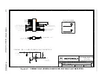
The Serial Communications Port 1, SCI1, is attached to this connector. Refer to
for the connection information.
2.22.15 Serial Peripheral Interface Expansion Connector
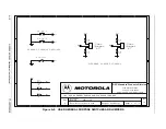
The Serial Peripheral Interface, SPI, is attached to this connector. Refer to
the connection information.
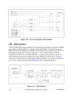
2.22.16 CAN Expansion Connector
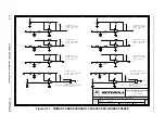
The CAN port is attached to this connector. See
for the connection
information.
Table 2-25. SCI1 Connector Description
J14
Pin #
Signal
1
TXD1
2
RXD1
3
GND
Table 2-26. SPI Connector Description
J13
Pin #
Signal
1
MOSI
2
MISO
3
SCLK
4
GND
Table 2-27. CAN Connector Description
J16
Pin #
Signal
1
MSCAN_TX
2
MSCAN_RX
3
GND
Содержание Digital DNA DSP56F807
Страница 2: ......
Страница 12: ...xii DSP56F807EVM Hardware User s Manual ...
Страница 53: ... DSP56F807EVM Schematics A 1 Appendix A DSP56F807EVM Schematics ...
Страница 72: ...A 20 DSP56F807EVM Hardware User s Manual ...
Страница 79: ......

