2-14
DSP56F807EVM Hardware User’s Manual
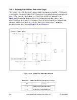
2.11 Primary UNI-3 Interface
Motor control signals from a family of motor driver boards can be connected to the EVM
board via the Primary UNI-3 connector/interface. The Primary UNI-3 connector/interface
contains all of the signals needed to drive and control the motor drive boards. These
signals are connected to various groups of the DSP’s input and output ports; A/D, TIMER
and PWM Port A. The header, JG14, is used to select between the Back-EMF and Motor
Phase Current signals. Refer to
for the pin out of the Primary UNI-3 connector,
J1.
Table 2-6. Primary UNI-3 Connector Description
J1
Pin #
Signal
Pin #
Signal
1
PWM_AT
2
Shield
3
PWM_AB
4
Shield
5
PWM_BT
6
Shield
7
PWM_BB
8
Shield
9
PWM_CT
10
Shield
11
PWM_CB
12
GND
13
GND
14
+5.0V DC
15
+5.0V DC
16
3.3V DC
17
Analog GND
18
Analog GND
19
15V DC
20
Analog -15V DC
21
Motor DC Bus
Voltage Sense
22
Motor DC Bus
Current Sense
23
Motor Phase A
Current Sense
24
Motor Phase B
Current Sense
25
Motor Phase C
Current Sense
26
Motor Drive
Temperature
Sense
27
NC
28
Shield
29
Motor Drive Brake
Control
30
Serial COM
31
PFC PWM
32
PFC Inhibit
33
PFC Zero Cross
34
Zero Cross A
35
Zero Cross B
36
Zero Cross C
Содержание Digital DNA DSP56F807
Страница 2: ......
Страница 12: ...xii DSP56F807EVM Hardware User s Manual ...
Страница 53: ... DSP56F807EVM Schematics A 1 Appendix A DSP56F807EVM Schematics ...
Страница 72: ...A 20 DSP56F807EVM Hardware User s Manual ...
Страница 79: ......

