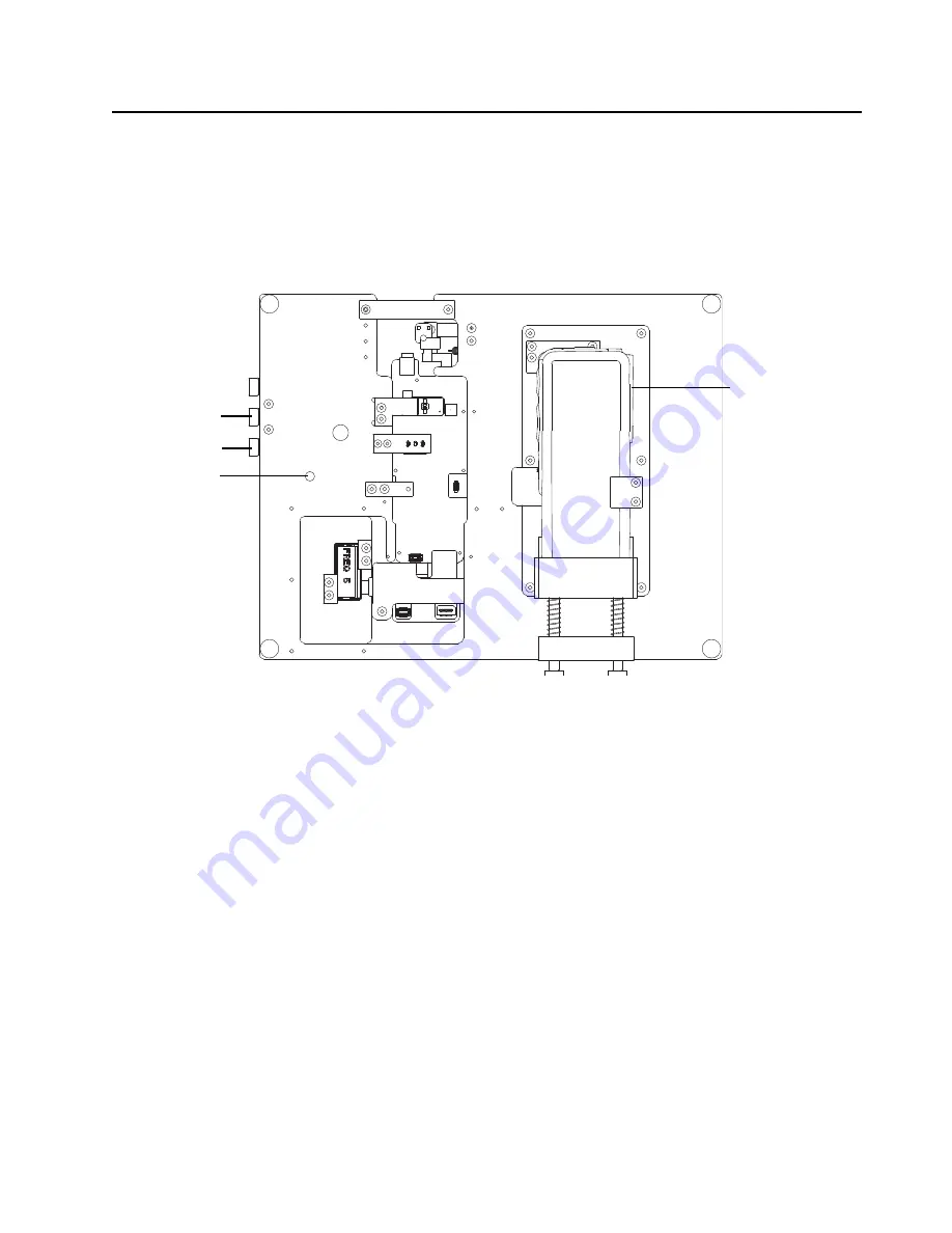
Debugging Fixture:
Powering up Covert Board
9-7
9.7
Powering up Covert Board
1. Connect the positive terminal to the positive side of the power supply and connect the
negative terminal to the negative side. Set the power supply voltage level to 7.5V and current
to 4Amps.
2. Switch on the board by using the On/Off switch.
3. A green LED will light up once the board is switched on. Use the display to observe any error
message.
Figure 9-11. Power up Covert board
GCAI
Interface
-ve terminal
+ve terminal
On/Off switch
Содержание Astro APX 3000
Страница 1: ...APXTM TWO WAY RADIOS APX 3000 DETAILED SERVICE MANUAL ...
Страница 2: ......
Страница 4: ...Notes ...
Страница 6: ...vi Document History Notes ...
Страница 10: ...x Table of Contents Notes ...
Страница 12: ...xii List of Tables Notes ...
Страница 18: ...xviii List of Figures Notes ...
Страница 22: ...xxii CommercialWarranty Notes ...
Страница 46: ...3 20 Theory of Operation Main Board Notes ...
Страница 84: ...3 58 Theory of Operation Bluetooth Notes ...
Страница 147: ...Troubleshooting Waveforms Clocks 6 3 6 2 2 4 MHz Clock Trace 1 Trace recorded at R6113 Figure 6 2 4 MHz Clock Waveform ...
Страница 154: ...6 10 Troubleshooting Waveforms Audio SSI 6 3 4 BCLK Trace 1 Trace recorded at R6107 Figure 6 9 Audio SSI BCLK Waveform ...
Страница 156: ...6 12 Troubleshooting Waveforms RX SSI 6 4 2 DA Trace 1 Trace recorded at R2805 Figure 6 11 RX SSI DA Waveform ...
Страница 157: ...Troubleshooting Waveforms RX SSI 6 13 6 4 3 FSYNC Trace 1 Trace recorded at R2804 Figure 6 12 RX SSI FSync Waveform ...
Страница 159: ...Troubleshooting Waveforms TX SSI 6 15 6 5 2 DA Trace 1 Trace recorded at R2817 Figure 6 14 TX SSI DA Waveform ...
Страница 160: ...6 16 Troubleshooting Waveforms TX SSI 6 5 3 FSYNC Trace 1 Trace recorded at R2807 Figure 6 15 TX SSI FSync Waveform ...
Страница 161: ...Troubleshooting Waveforms SPI 6 17 6 6 SPI 6 6 1 CLK Trace 1 Trace recorded at R2803 Figure 6 16 SPI CLK Waveform ...
Страница 162: ...6 18 Troubleshooting Waveforms SPI 6 6 2 CS Trace 1 Trace recorded at R6602 Figure 6 17 CS Waveform ...
Страница 164: ...6 20 Troubleshooting Waveforms I2C BUS 6 7 2 SCL 5V Trace 1 Trace recorded at R2204 Figure 6 19 I2C Bus SCA 5V Waveform ...
Страница 165: ...Troubleshooting Waveforms I2C BUS 6 21 6 7 3 SDA Trace 1 Trace recorded at R6209 Figure 6 20 I2C Bus SDA Waveform ...
Страница 169: ...Troubleshooting Waveforms USB 6 25 6 10 USB 6 10 1 D Trace 1 Trace recorded at TP F_GCAI_USB Figure 6 24 USB D Waveform ...
Страница 170: ...6 26 Troubleshooting Waveforms USB 6 10 2 D Trace 1 Trace recorded at TP F_GCAI_USB Figure 6 25 USB D Waveform ...
Страница 172: ...6 28 Troubleshooting Waveforms SDRAM 6 11 2 CLKX Trace 1 Trace recorded at TP6308 Figure 6 27 SDRAM CLKX Waveform ...
Страница 208: ...6 64 Troubleshooting Waveforms LF CW on Spectrum Analyzer Notes ...
Страница 222: ...7 14 Troubleshooting Tables List of Board and IC Signals Notes ...
Страница 282: ...8 60 Schematics Boards Overlays and Parts Lists Main Board Block UHF1 84012513001_A Notes ...
Страница 338: ...8 116 Schematics Boards Overlays and Parts Lists Main Board Block 700 800 MHz 84012501002 Notes ...
Страница 390: ...8 168 Schematics Boards Overlays and Parts Lists Main Board Block VHF 84012512001_A Notes ...
Страница 456: ...9 8 Debugging Fixture Powering up Covert Board Notes ...
Страница 468: ...Glossary 10 Glossary Notes ...
Страница 472: ...Index 4 Index Notes ...
Страница 473: ......


