


22
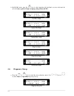
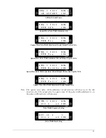
F R Q : 1 . 0 0 0 0 K H z
F M O F F S B 7
FM Off
F R Q : 1 . 0 0 0 0 K H z
F M 4 0 0 H z S B 7
FM On, Internal 400Hz Source
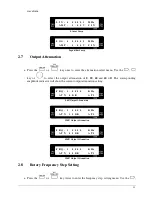
F R Q : 1 . 0 0 0 0 K H z
F M 1 0 0 0 H z S B 7
FM On, Internal 1000Hz Source
F R Q : 1 . 0 0 0 0 K H z
F M E X T E R N S B 7
FM On, External Source
2.13
Notice of Operating
a.
For Waveform Measurement :
•
The FG 700S/F series Func Out output impedance is 50
Ω
, so
the oscilloscope input impedance
must be matched to 50
Ω
. Use the coaxial cable for characteristic impedance 50
Ω
in connecting
with both FG 700S/F series Func Out and oscilloscope input terminal.
•
Minimizing the cable length and cable stray capacitance is very important for the best
performance.
•
Because the function generator output is a wideband signal, every connecting path including the
transmitter or receiver, must be impedance matched to 50
Ω
, in order to avoid the reflection from
load and the undesired testing results.
b.
Output Voltage Definition :
•
For FG 700S/F series output impedance is 50
Ω
, if the load is greater enough than 50
Ω
, it will
result in the load voltage drop equal to the open circuit of the function generator output,
approximately. If the load is 50
Ω
, the load voltage drop is equal to one half of the open circuit of
the function generator output voltage.
c.
For Small Signal Output :
•
For small signal output, it is suggested to add the attenuator, for example: -20 dB, to the function
generator output, and adjust the desired output level. This is the method for getting the best
Содержание FG 700F Series
Страница 1: ...Operating Manual FG 700S F Series Direct Digital Synthesis Function Generator...
Страница 2: ......
Страница 6: ......
Страница 30: ...ZOMG 700ME 1B...


