background image

26/11/08  22250-I

© MOSA

REV.0-11/08

MAGIC WELD 200

AG

6

Ricambi
Spare parts
Piéces de rechange

Ersatzteile
Tabla de recambios

1

2

3

4

5

6

7

8

9

10

11

12

13

14

15

16

17

18

20

19A

19B

19C

22

23

24

25

26

21

(qm)

Содержание Magic Weld 200

Страница 1: ...MAGIC WELD 200 222509003 GB 0 3 1 0 18 11 08 22262M00 preparato da UPT approvato da DITE ENGLISH ...

Страница 2: ...maximum at load take up Weight 57 Kg Acoustic Power 74 dBA to 7m Electrical components of the machine Permanent magnet alternator the alternator has 2 galvanically separated windings one for welding and the other for the auxiliary output Tick over solenoid an electromagnet in absence of load When the load is present welding or auxiliary output the electromagnet is not supplied any more and the eng...

Страница 3: ...ill continue to satisfy the needs of its clients as well as to improve the transparency and the communications regarding all the company s actives in accordance with the official procedures and in harmony with the MOSA Manual of Quality The advantages for MOSA clients are Constant quality of products and services at the high level which the client expects Continuous efforts to improve the products...

Страница 4: ...ING AND TRANSPORT M 6 15 ASSEMBLING CTM MW 200 M 25 SET UP FOR OPERATION M 26 ENGINE STARTING M 27 STOPPING THE ENGINE M 31 CONTROLS M 34 USE AS A WELDER M 34 2 CHECKING AN ADJUST THE MAXIMUM WELDING CURRENT M 34 3 PARALLEL ENGINE DRIVEN WELDER M 37 USE AS A GENERATOR M 40 2 TROUBLE SHOOTING M 43 MAINTENANCE M 45 STORAGE CUST OFF M 53 DIMENSIONS M 55 RECOMMENDED ELECTRODES M 60 ELECTRICAL SYSTEM L...

Страница 5: ...laws in force in the matter In no case MOSA division of B C S S p A will be held responsible for any damaga direct or indirect in relation with the use of the given information MOSA division of B C S S p A does not take any responsibility about the shown information on firms or individuals but keeps the right to refuse services or information publication which it judges discutible unright or illeg...

Страница 6: ...laces protected from dampness and heat You must take into account that some figures contained in it want only to identify the described parts and therefore might not correspond to the machine in your possession INFORMATION OF GENERAL TYPE In the envelope given together with the machine and or set you will find the manual for Use Maintenance and Spare Parts the manual for use of the engine and the ...

Страница 7: ...directives is part of the declaration of conformity included in any machine standard equipment Here below the adopted symbol CE marking is clearly readable and unerasable and it can be either part of the data plate A or placed as a sticker near the data plate B A B Furthermore on each model it is shown the noise level value the symbol used is the following The indication is shown in a clear readab...

Страница 8: ...vel It s admitted overload of 10 each hour every 12 h In an approximative way one reduces of 1 every 100 m altitude and of 2 5 for every 5 C above 25 C ACOUSTIC POWER LEVEL ATTENTION The concrete risk due to the machine depends on the conditions in which it is used Therefore it is up to the end user and under his direct responsibility to make a correct evaluation of the same risk and to adopt spec...

Страница 9: ... to the use of these instructions will not be considered because these are only indicative Remember that the non observance of the indications reported by us might cause damage to persons or things It is understood that local dispositions and or laws must be respected Skin contact Eyes contact Ingestion Suction of liquids from lungs Inhalation Wash with water and soap Irrigate with plenty of water...

Страница 10: ...chine as well as potential hazards and dangers for persons and things This symbol is used to draw your attention to the fact that the welder is being used correctly and that the machine or equipment used operates perfectly Use only with safety clothing It is compulsory to use the personal pro tection means given in equipment Use with safe materials only Never use water to put out fires on electric...

Страница 11: ...ings and or of communication check wirings and so on in the immediate vicinity Radio and television receptors and transmettors Computer and other checking devices Critical devices for safety and or for industrial checks Peapol who for instance use pace maker hearing aid for deaf or something and else Devices used for rating and measuring The immunity of other devices in the operation area of the w...

Страница 12: ...increase of the temperature Make sure that the machine does not move during the work block it possibly with tools and or devices made to this purpose MOVES OF THE MACHINE At any move check that the engine is off that there are no connections with cables which impede the moves PLACE OF THE MACHINE AND OR EQUIPMENTS 1 5 m 1 5 m 1 5 m GAS DI SCARICO Maximum leaning of the machine in case of dislevel ...

Страница 13: ...MAGIC WELD 200 M 2 7 MOSA REV 0 11 08 26 11 08 22250 I Installazione Installation Installation Luftzirkulation Instalación ...

Страница 14: ...mmediately our Technical Service For eliminating the packing materials the User must keep to the norms in force in his country 1 Take the machine C out of the shipment packing Take out of the envelope A the user s manual B 2 Fit the handle as shown in the instructions fitting screws and spanner are supplied 3 Read the user s manual B the plates fixed on the machine the data plate 2 B A 1 C In case...

Страница 15: ...t the machine and assemble the parts as shown in the drawing The CTM accessory cannot be removed from the machine and used separately actioned manually or following vehicles for the transport of loads or anyway for used different from the machine movements ATTENTION ...

Страница 16: ...ell venti lated area Do not refuel in the presence of flames Avoid spilling fuel Any eventual spilled fuel and fumes are flammable Clean any dispersions of fuel before starting up the motor AIR FILTER Check that the dry air filter is correctly installed and that there are no leaks around the filter which could lead to infiltrations of non filtered air to the inside of the motor WARNING Do not use ...

Страница 17: ...STARTER GRIP Lightly pull the start up knob 73 until meeting resistance then pull decisively ATTENTION Allow the start up knob to re enter slowly avoiding having it knock against the motor and thereby damaging the start up system 4 When the engine is started the machine re aches maximum engine speed immediately 4000 rpm for 6 7 seconds after which the engine speed automatically decreases to minimu...

Страница 18: ...r For shut down the motor in case of emergency turn the motor switch 28 to OFF In normal conditions wait for the engine to reach minimum speed automatically 6 7 seconds after the load has been excluded Turn the engine in these conditions for a few minutes so that it can cool down and then turn the engine switch 28 to OFF Turn the fuel valve to the OFF position ENGINE SWITCH FUEL VALVE NEW MAGIC WE...

Страница 19: ...fler Stop control Oil drain tap Starting push button Welding current regulator Remote control socket Prises de soudage Prises de soudage Prise de mise à terre Prises de courant en c c Filtre air moteur Jauge niveau huile moteur Bouchon remplissage huile moteur Bouchon réservoir Silencieux d échappement Commande stop Bouchon décharge huile moteur Commande manuelle démarrage Régulateur courant souda...

Страница 20: ...ing pincer is connec ted as near as possible to the work station ATTENTION To reduce the risk of electromagnetic interfe rence keep the welding cable length short and keep them on or near the ground If possible welding operations should not be done near sensitive electronic devices If interference continues to occur adopt additional measures shift the group use shielded cables line filters shield ...

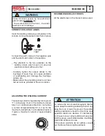
Страница 21: ...From Fig 1 proceed as follows when the machine idles engine cold Keep pin A locked 8 mm spanner and un screw nut B 7 mm spanner Again with pin A locked turn nut C clockwise 7 mm spanner 1 3 mm The more it is ex tended the more the idle speed increases Tighten nut B on pin A and check the idling speed Minimum welding voltage TOO HIGH From Fig 1 proceed as follows When the machine idles engine cold ...

Страница 22: ...nopola di saldatura al massimo Ruotare lentamente il trimmer in senso orario affinché la corrente di saldatura arrivi a 200A Every time either the board or the current sensor is changed it is necessary to check the max welding current and if it is the case to set it as follows Attach de pcb on his iron plate connect all wives and all connectors Put the dip switch as drawing Dip Switch Rotate the t...

Страница 23: ...selves and the two negative welding sockets bethween themselves To effect the connection ask for the accessory K2X150 ATTENTION use fit cables and tight at the connection point How to proceed start the machine putting the two welding handles T in the wanted position half of the total current put in parallel with the right cables proceed with welding 18 11 08 22262 GB MAGIC WELD 200 ...

Страница 24: ...xtension length limited to 100 200 metres This limitation of circuit extension length is fundamental for safety The cables must be SUITED to the environment in which they are to be used Bear in mind that at temperatures below 5 C PVC cables become rigid and the PVC insulation tends to split at the first crease Using double insulated equipment is advisable this is identifiable by the symbol and for...

Страница 25: ...ce 3 Disconnect the welding and auxiliary power cables Use a voltmeter to check that there is 48 Vac at the outputs in weld and approximately 145 Vac between the outputs in generation Carry out the check when the engine idles disconnect one of the two wires to the solenoid 1 Chopper welding bridge broken 2 Faulty circuit 3 Faulty alternator 1 replace the fuse 10A retarded for version 230V 15A reta...

Страница 26: ...rth 2 welding chopper bridge not insulated from earth 3 power cables not insulated from earth 4 faulty circuit 1 Disconnect all the outputs 3 for welding which go to the chopper bridge and 4 for auxiliary power which go to the circuit board Use a multimeter to check the insulation of the alternator 2 disconnect the 3 welding cables the and for welding the black wire and the connector which go to t...

Страница 27: ...nd topping up or replace ment of fluids such as fuel oil and the regular cleaning of the machine Repairs refers to the substitution of worn or damaged parts and repairs should be carried out by Authorized Service Centres Refer to the Engine Manufacturer s Manual for the maintenance instructions for the engine Periodic maintenance should be performed according to the schedule shown in this manual O...

Страница 28: ...luids potentially dangerous such as lubricating oil The dismantling of metallic parts liable to cau se injuries or wounds must be made wearing heavy gloves and using suitable tools The getting rid of the various components of the machine must be made accordingly to rules in force of law a o local rules Particular attention must be paid when getting rid of lubricating oils inflamable liquids such a...

Страница 29: ... MOSA REV 1 03 10 26 11 08 22250 I MAGIC WELD 200 M 53 Dimensioni Dimensions Dimensions Abmessungen Dimensiones 517 611 481 ...

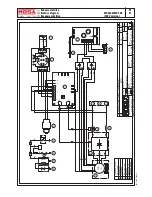
Страница 30: ...ote control PCB A Alternateur H Prise 230V monophasé I Prise 110V monophasé R Unite contrôle soudage T Régulateur courant soudage Y Pont diodes soudage Z Prises de soudage W Rèactance c c F1 Electro aimant accélérateur S2 Transmetteur niveau huile F3 Bouton stop G3 Bobine allumage H3 Bougie allumage W6 Senseur de hall R8 Inverteur S8 Voyant Surcharge Z8 Télécommande fiche A Generator H Steckdose 2...

Страница 31: ...f n Desi Dis n Exp Page n Dwg n Disegnatore La MOSA si riserva a termini di legge la proprieta del presente disegno con divieto di riprodurlo o comunicarlo a terzi senza sua autorizzazione R B R Z 3 GS A W 230V 16A H W6 Y P1 P3 P2 Sol 1 Sol 2 Si Su Ri Ru Tu Ti Y 1 2 3 4 5 6 7 8 9 10 11 12 R 06 11 2008 T1 S1 R1 T2 S2 R2 T2 S2 R2 S1 R1 R8 B R S8 T1 KEY COLOR LEGENDA COLORI NERO BLACK R ROSSO RED B G...

Страница 32: ...of n Desi Dis n Exp Page n Dwg n Disegnatore La MOSA si riserva a termini di legge la proprieta del presente disegno con divieto di riprodurlo o comunicarlo a terzi senza sua autorizzazione 06 11 2008 KEY COLOR LEGENDA COLORI NERO BLACK R ROSSO RED B GIALLO YELLOW Y BL BLU BLUE W BIANCO WHITE MARRONE BROWN BR R B R T1 S1 R1 T2 S2 R2 T2 S2 R2 S1 R1 T1 B Y B Y Y B R B W BR B Y BL Z 3 GS A W P1 P3 P2...

Страница 33: ...EUTRALBONDEDTOFRAME NEUTROCOLLEGATOAMASSA 65 60 Hz A 10 50 15 55 500 300 V ST RS 0 200 100 TR 0 h HOURMETER I 0 EA 1 25 20 125 1 3 13 18 17 16 20 21 22 12 21 22 23 14 11 8 2 19 15 4 5 6 EA 1 12 50 Hz 50 Hz 3 EA 1 4 12 TS 0000 GE TS 0000 GE V le Europa 59 20090 CUSAGO MI ITALY Tel 39 02 90352 1 fax 39 02 90390466 0987654321 TYPE SERIAL N 22 03 00 R1GB The requested data are to be found on the data ...

Страница 34: ...6 11 08 22250 I MOSA REV 0 11 08 MAGIC WELD 200 AG 6 Ricambi Spare parts Piéces de rechange Ersatzteile Tabla de recambios 1 2 3 4 5 6 7 8 9 10 11 12 13 14 15 16 17 18 20 19A 19B 19C 22 23 24 25 26 21 qm ...

Страница 35: ...270080 PROFILATO GOMMA 21 M306418310 GUARNIZIONE L MT 1 22 M222504126 LAMIERA PROTEZIONE REATTORE 23 M222501050 BARELLA 24 M222504100 REATTORE DI LIVELLO 25 M222501372 PIASTRA SUPPORTO REATTORE 26 M256011035 ANTIVIBRANTE Pos Rev Cod Descr Note 1 M222503045 ALTERNATOR SUPPORT FLANGE 2 M306412200 HONDA ENGINE GX270 3 M222503061 SPACER 4 M222418263 SMALL PLATE 5 M222503025 STATOR 6 M222503047 HUB SHA...

Страница 36: ...26 11 08 22250 I MOSA REV 1 03 10 MAGIC WELD 200 AG 7 Ricambi Spare parts Piéces de rechange Ersatzteile Tabla de recambios 1 2 2a 3 4 5 6 7 8 9 10 11 12 13 14 15 16 17 18 19 20 ...

Страница 37: ...LO OR 2037 15 M222507020 PANNELLO FRONTALE superiore 16 M270009701 POTENZIOMETRO 17 M765009911 CAPPUCCIO X CONNETTORE 18 M765009910 CONNETTORE 19 M222509632 SCHEDA REMOTE CONTROL 20 M222440543 KIT POTENZIOMETRO MANOPOLA Pos Rev Cod Descr Note 1 M222507205 FRONT PANEL 2 M22250c001 WARNING LIGHT CABLES INCLUDED 230V 2a M22251c001 WARNING LIGHT CABLES INCLUDED 110V 3 M307047250 EEC SOCKET 16A 110V 2P...

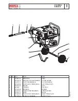
Страница 38: ...70 TAPPO PER MANIGLIA CAP FOR HANDLE 4 222500183 PIASTR SX FISS MANIGLIA LEFT FIXING PLATE 5 222421160 ASSALE AXLE 6 6075020 COPIGLIA PIN SPLIT 7 222422038 RONDELLA WASHER 8 222421051 PIEDE DI STAZIONAMENTO PARKING STAND 9 222421170 RUOTA WHEEL 10 222500184 PIASTR DX FISS MANIGLIA RIGHT FIXING PLATE 11 222429359 SPINA DI SICUREZZA SAFETY PLUG 1 2 3 4 8 9 11 5 6 7 10 ...

Отзывы: