www.morsona.com
[ 12 ]
[ 13 ]
Flue Connection
The stove is supplied from the factory with round blanking plates blocking off the top and rear flue exits
(behind the rear shield plate). A cast iron flue collar is placed inside the firebox during transit.
Use a 24 MSG black chimney connector or listed double wall chimney connector. Refer to local codes
and the chimney manufacturer’s instructions for precautions required for passing a chimney through a
combustible wall or ceiling. Remember to secure the chimney connector to the product using a mini-
mum of three screws to each adjoining section.
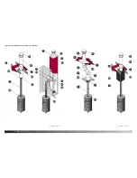
The flue collar can be fitted to the rear outlet. Simply knock out the round panel on the rear plate to
reveal the cast iron plate. Untwist the blanking plate and the flue collar and swap their positions. Re-
secure by pushing down and tighten the enclosed screws.
Position the stove and connect to the flue system.
Connection to the existing chimney - using single wall or double wall chimney connector.
A chimney connector is the double-wall or single-wall pipe that connects the stove to the chimney. The
chimney itself is the masonry or prefabricated structure that encloses the flue. Chimney connectors are
used only to connect the stove to the chimney.
Double-wall connectors must be tested and listed for use with solid-fuel burning appliances. Single-
wall connectors should be made of 24 gauge or heavier gauge steel. Do not use galvanized connector;
it cannot withstand the high-temperatures that smoke and exhaust gases can reach, and may release
toxic fumes when under high heat. The connector must be 6 inches (150mm) in diameter.
if possible, do not pass the chimney connector through a combustible wall or ceiling.
if passage through a combustible wall is unavoidable, refer to the sections on Wall
pass- Throughs. Do not pass the connector through an attic, a closet or similar
concealed space when installing the chimney connectors.
It is important to keep the flue gases moving smoothly in the right direction. Do not vent into a large
void; rather form one continuous section all the way up. Use mild bends (e.g. 45º vs. 90º) rather than
sharp angles where a change of direction is required. All parts of the venting must be accessible for
cleaning purposes.
In horizontal runs of chimney, maintain a distance no less than18 inches from the ceiling. Keep it as
short and direct as possible, with no more than two 90 degree turns. Slope horizontal runs of connector
upward 1/4 inch per foot (20 mm per metre) going from the stove toward the chimney. The recommen-
ded maximum length of a horizontal run is 3 feet (1 metre), and the total vertical length should be no
longer than 8 feet (2.5 metres).
Information on assembling and installing connectors is provided by the manufacturer’s instructions.
Be sure the installed stove and chimney connector are correctly distance from near by combustible
materials. See the clearance paragraph page 13.
Where passage through a wall or partition of combustible construction is desired, the installation shall
conform to CAN/CSA-B365.
Clearances to combustible surfaces
Distance to walls and lintel
When the stove is positioned near combustible materials, observe all current local and national buil-
ding regulations with regards to clearances. Whatever regulations apply to your area, do not in any case
install the stove within 8 inches of combustible materials from the sides or 16 inches above the top of
the stove (fireplace installations require greater clearances above the stove - see below in the clearance
chart). These distances may need to be increased if the materials (precious furniture) are sensitive to
heat. Note also that wallpaper and other decorative materials may become detached with the effects of
heat and care should be taken to ensure that they do not fall onto the stove in such an event.
When the stove is positioned near non-combustible materials, a gap of 4 inches or more is recommen-
ded for cleaning purposes and to ensure that heat circulates around the stove and out into the room.
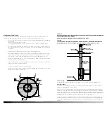
Clearance requrements
FreeSTANDiNg reSiDeNTiAL iNSTALLATiON TOp veNT
using single wall connector
USA
Canada
A. Sidewall to unit
15”
381 mm
B. Backwall to unit
1”
26 mm
C. Cornerwall to unit
2½”
64 mm
D. Sidewall to connector
21”
533 mm
E. Backwall to connector
7”
178 mm
F. Cornerwall to connector
8½”
216 mm
G. Unit to ceiling
47”
1194 mm
Minimum clearances to combustibles:
Backwall
Adjacent wall
Adjacent wall
Sidewall


