


- 2 -
Figure 1-1
switch front panel
4 LED Indicators
LED
Function
PWR
Lit: Power on.
LINK/ACT
Lit: indicate the link through that port is successfully
established.
Blink: indicate that the Switch is actively sending or
receiving data over that port.
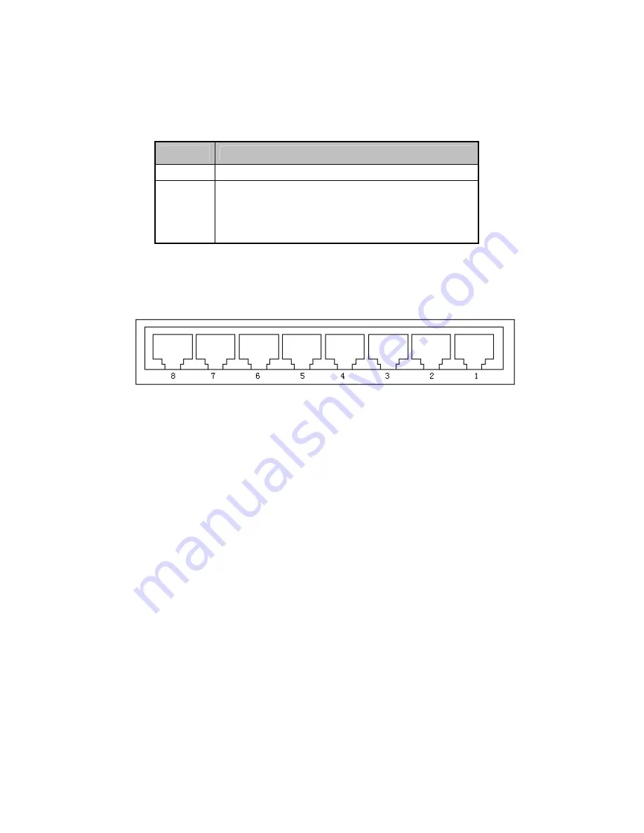
5. Switch Rear Panel
Figure 1-2 shows a rear panel of the switch.
Figure 1-2
switch rear panel
Ports
These ports are connection points for PCs and other network devices, such as additional
switches.
Power
The power port is where you will connect the external power adapter. (The power port of
the switch on the side way)
6. Installing the Switch
This part describes how to install your Fast Ethernet Switch and make connections to it.
Please read the following topics and perform the procedures in the order being presented.
Desktop Installation
To install the Switch on desktop, simply follow the next steps:
Step 1: Place the Switch on desktop near an AC power source.
Step 2: Keep enough ventilation space between the Switch and the surrounding objects.
Step 3: Connect your Switch to network devices.
A. Connect one end of a standard network cable to the 10/100 RJ-45 ports on the Back of
the Switch.
B. Connect the other end of the cable to the network devices such as printer servers,
workstations or routers…etc.
Step 4: Supply power to the Switch.
A. Connect one end of the power cable to the Switch.


