Visionary Boards
UPDATED AS OF: 09/14/2021
1 of 7
INSTRUCCIONES DE ENSEMBLAJE
NO LA TIRE
INSTRUCTIONS DE MONTAGE
NE PAS JETER
ASSEMBLY INSTRUCTIONS
DO NOT THROW AWAY!
Страница 1: ...Visionary Boards UPDATED AS OF 09 14 2021 1 of 7 INSTRUCCIONESDEENSEMBLAJE NO LA TIRE INSTRUCTIONSDEMONTAGE NE PAS JETER ASSEMBLYINSTRUCTIONS DO NOT THROW AWAY ...
Страница 2: ...PDATED AS OF 09 14 2021 2 of 7 Hardware P1 Glass Board P2 Tray Mount P3 Tray x1 x1 x1 A Outer Cap B Wall Mount C M5 x 34mm D Drywall Anchor E Masonry Anchor F M6 x 10mm x6 8 10 x6 8 10 x8 10 12 x6 8 10 x6 8 10 x2 ...
Страница 3: ...tps moorecoinc com register Email support moorecoinc com Previo a comenzar el proceso de ensamblaje favor de revisar las instruccionesyasegurarsequecuentacon todas las partes y materiales necesarios Es posible que los muebles grandes o pesados requieran mas de una persona para ensamblarlos correctamente Por favor contacte al fabricante directamente si tiene alguna duda o pregunta antes de continua...
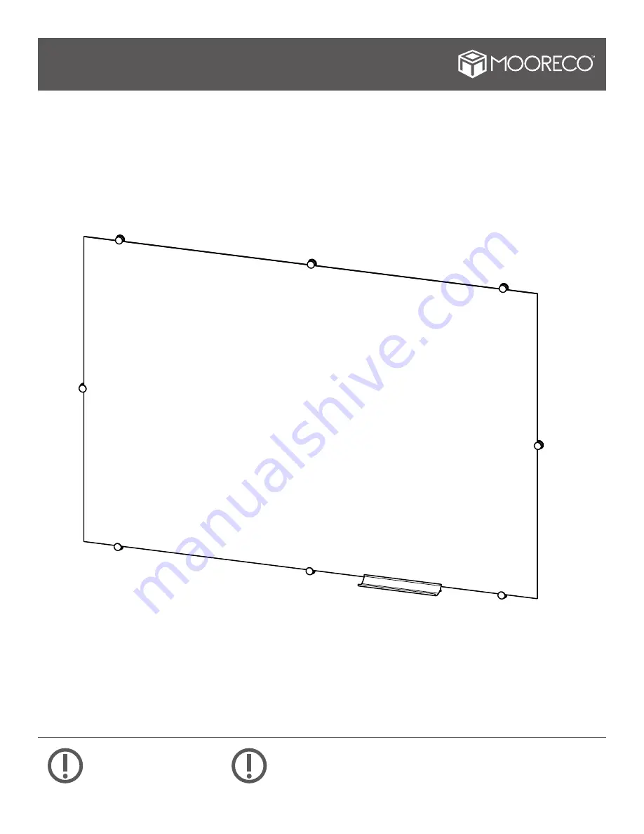
Страница 4: ...sonry drill only 1 4 holes For 6 ft or 8 ft boards see next step for additional predrill placement STEP2 For 6 ft and 8 ft long boards add holes for additional wall mount clips along long edges of boards 6 ft boards will get two additional clips and 8 ft boards will get four additional clips equally spaced as shown Spacing from top bottom and left and right edges of boards will be the same as prev...
Страница 5: ...rews should be tight enough to hold all mounts in place STEP4 Masonry Wall 1 4 Predrill Masonry Wall 1 4 Predrill Masonry Wall 1 4 Predrill E Drywall 1 4 Predrill Stud Wall 1 8 Predrill C B D Drywall Stud Wall Top Bottom Left Right Adhesive Pad Centerline Place adhesive pads along backside of board Use two pads per board equally spaced along the center For 6 and 8 long boards installed vertically ...
Страница 6: ...TED AS OF 09 14 2021 6 of 7 Drill two holes 3 apart 1 above the bottom edge of where your board will be Secure the Tray Mount P2 with two screws D and inserts as required 3 1 Tray STEP2 Bottom Edge of Board P3 F C P2 ...
Страница 7: ...op mounts and push them down Screw in top outer caps to hold panel in place Finally push in left and right side mounts and screw in outer caps to secure panel Apply pressure to front face of board to engage adhesive pads with wall and lock board in place UPDATED AS OF 09 14 2021 7 of 7 THIS COMPLETES ASSEMBLY INSTRUCTION ...