background image

RIY

18

   The Interface Solution Experts

Operation

Operating the RIY is limited to viewing the LCD for
input values, zero or span reading, or problem codes;
and performing quick ranging using the push buttons.
Units that are not equipped with an LCD have no
definitive operating procedures.

The LCD is the only visual indicator on the RIY;
without it, the user has no on-the-spot, visual indica-
tion as to the settings or operational status of the RIY.

When a non-LCD unit is calibrated with standard
ranging methods, it can be reliably installed in a
process loop, but it can not be quick ranged and must
be removed from the loop for subsequent calibrations.

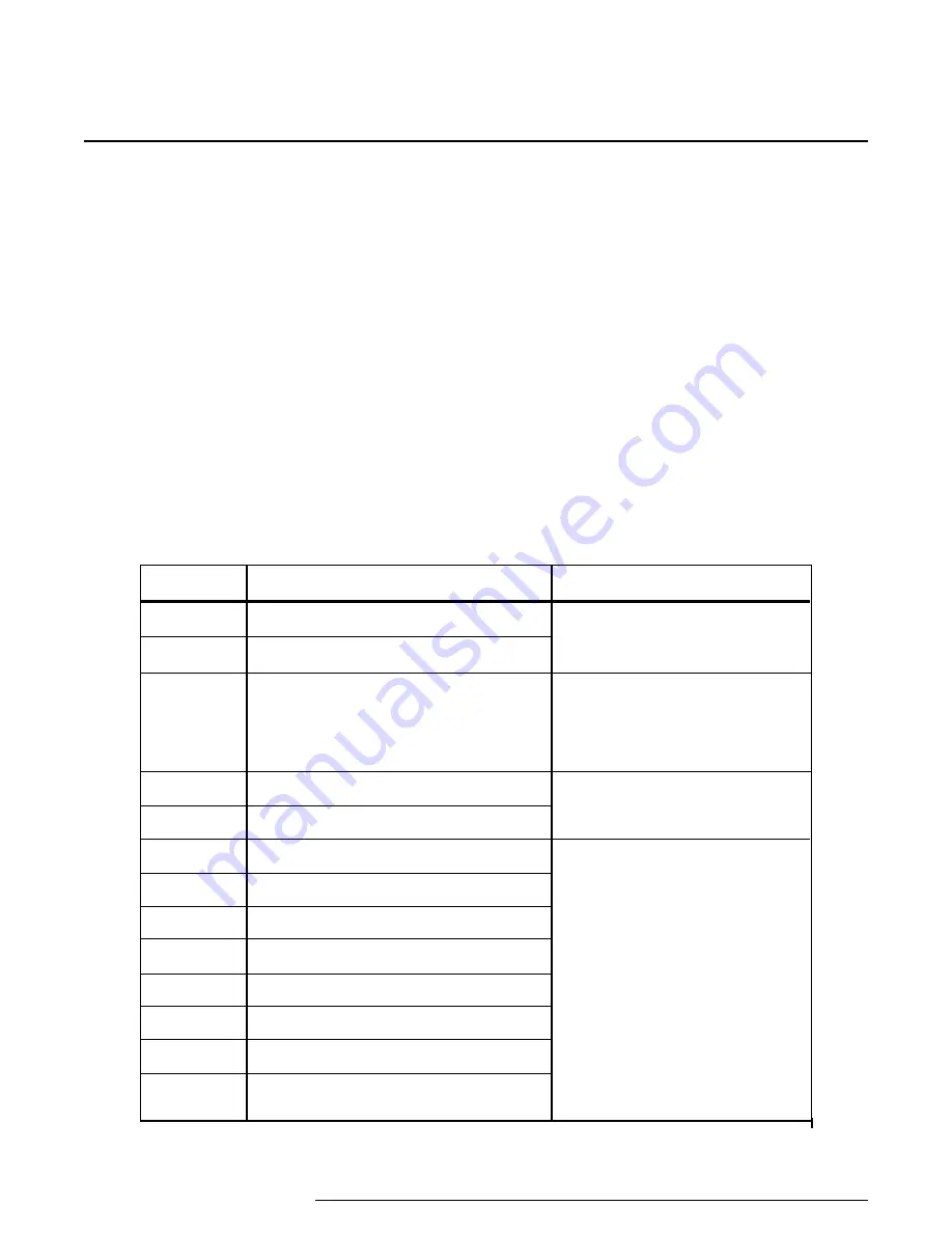
Problem

Failed RAM test on power up

Failed ROM checksum on power up

Failed EEPROM checksum on power up

EEPROM did not write properly

EEPROM RTD table is bad

Lead # 1 or 4 is open (2-wire sensor)

Lead #4 is open

Lead #3 is open

Lead #2 is open

Lead #1 is open

RTD/Element #1 is open

RTD/Element #2 is open

RTD/Element #3 is open

Code

P1

P2

P3

P4

P5

P6 

(or 

EL1

)

P7 

or 

L4

P8 

or 

L3

P9 

or 

L2

P10 

or 

L1

P11 

or 

EL1

P12 

or 

EL2

P13 

or 

EL3

Table 4. 

 Self-diagnostic Problem Codes

Remedy

Cycle dc power; if problem persists,

return unit per instructions on the

back cover of this manual

If power is lost during calibration,

repeat calibration; otherwise, cycle

dc power; if problem persists,

return unit per instructions on the

back cover of this manual

Cycle dc power; if problem persists,

return unit per instructions on the

back cover of this manual

Repair sensor or wiring

The LCD

The LCD also displays problem codes resulting from
the RIY’s self-diagnostics.  Codes indicate malfunc-
tions or discrepancies detected by the RIY’s micro-
processor at power-up, during calibration, or in the
operate mode.  Table 4 contains these codes, the
problem indicated, and the remedy for each.

During normal operation, the LCD typically displays
the applied input value.  As the input changes, the
read-out of the LCD changes accordingly.

The LCD can also display the zero and span settings
during normal operation when the appropriate front
panel push button is pressed.

Содержание RIY

Страница 1: ...RIY RIY Programmable Isolated RTDTransmitter May 2016 149 733 00 D Programmable Isolated RTD Transmitter ...

Страница 2: ...Table of Contents Introduction 1 Description 1 Calibration 3 Installation 13 Operation 14 Maintenance 19 ...

Страница 3: ...r quick ranging Switches are used to configure several functional characteristics of the RIY Each of these switches is accessible without disassembling the unit The switch selectable features include Readouts in degrees Celsius or Fahrenheit or ohms only on units with LCD s Sensor type and number to be input to the RIY Upscale downscale drive Quick standard ranging Keyboard lockout enable The RIY ...

Страница 4: ... table 2 for accuracy by input type Isolation Galvanic isolation between input and output up to 1000 Vdc Stability 0 1 of calibrated span for 6 months Ripple 10 mV P P maximum up to frequencies of 120 Hz measured across a 250Ω load resistor RFI EMI Susceptability 30 V m abc 0 1 of ohms reading as defined by SAMA 33 1 HP and DIN units Ambient Temperature Effect All combined effect 0 006 of span C 1...

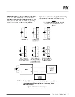
Страница 5: ... push buttons used to set zero and span full scale Figure 1 shows the layout of the membrane panel for both the HP and DIN style units Each push button is labeled with an Up or Down arrow inside a circular background that is contoured to the membrane panel surface The functions of the push buttons are labeled ZERO SPAN SAVE and CANCEL When the arrows are pressed individually or in certain simulta ...

Страница 6: ... quick ranging units with LCD s only decrement the trim value for the zero and 100 percent output levels in standard ranging cancel the calibration mode and returns the unit to normal operation when both are pressed simultaneously retains previous values Pressing the ZERO or SPAN Up and Down arrows simultaneously sets the unit to the calibrate mode if enabled through switch settings for that parti...

Страница 7: ...llowing features SW301 1 Displayed Temperature Type ON Sensor input displayed in Celsius OFF Sensor input displayed in Fahrenheit This switch determines the type of temperature units that will be displayed on the LCD If an ohms range is selected the display will show OHMS and this switch is ignored SW301 2 3 Number of Wires or Sensors These two switches determine the number of wires for a single s...

Страница 8: ... of R1 Differential 2 of R0 Differential 2 of R5 Differential 120Ω at 0 C α 0 00672 9 035Ω at 0 C α 0 00427 0 4000Ω 1000Ω at 0 C α 0 00285 Range2 3 200 to 850 C 328 to 1562 F 200 to 600 C 328 to 1112 F 200 to 510 C 328 to 950 F 200 to 650 C 328 to 1202 F 200 to 630 C 328 to 1166 F 200 to 630 C 328 to 1166 F 200 to 630 C 328 to 1166 F 185 to 540 C 301 to 1004 F 200 to 850 C 328 to 1562 F 550 to 800...

Страница 9: ...d representative zero and span full scale input values However quick ranging can only be per formed on units with an LCD The LCD operates independently from the highly accurate conversion circuits of the RIY Field calibra tion of the LCD itself is typically not required as the performance of the LCD does not affect the accuracy of the output However if the LCD readings drift beyond the accuracy ra...

Страница 10: ...with the SPAN push buttons varies only the full scale output value the zero reference point remains at the level it was last set to The zero percent output should always be trimmed before trimming the 100 percent output Standard Ranging Setup To perform standard ranging you need an input source dc power source and an output monitoring device Table 3 lists the calibration equipment and the equipmen...

Страница 11: ... is equal to a 12 mA output with a 250 Ohm resistor Similar calculations can be made over the 1 5 Vdc range with the following conversion formula V voltage reading 250Ω mA Table 3 RIY Calibration Equipment Standard Ranging Equipment Decade Resistance Box Voltmeter and Precision Resistor DC Power Source Specifications Accuracy of 0 01 or better Digital voltmeter accuracy of 0 005 or better 250Ω pre...

Страница 12: ...mA repeat steps 6 and 7 until 5 Vdc reading is obtained 9 Set input device for full scale input to RIY 10 To capture full scale input value press slowly the Up and Down SPAN push buttons simultaneously twice 11 Verify that voltmeter reading is 1 Vdc 4 mA This indicates that full scale value was captured successfully If voltmeter reads 5 Vdc repeat steps 9 and 10 until 1 Vdc reading is obtained 12 ...

Страница 13: ...to perform quick ranging and set SW301 6 to the off position for units with this switch functional for keyboard enable The settings entered during calibration are stored in an EEPROM when the SAVE push buttons are pressed These setting are retained until a subsequent calibra tion quick or standard ranging is performed If the latest settings are not saved before removing power or if the CANCEL push...

Страница 14: ...to table 2 the LCD will display HI or LO respectively The value entered must be within programmed table limits to be displayed 7 To change span full scale setting press the Up and Down SPAN push buttons simultaneously 8 Set 100 percent full scale input value shown on LCD to desired setting using the Up or Down SPAN push button to increment or decrement displayed value 9 When 100 percent input valu...

Страница 15: ...rence between them influences the 4 20 mA output of the RIY For example when resistance of one sensor RTD increases while the other remains constant the output of the RIY may also increase toward 20 mA If both inputs are varying increasing and decreasing in value the output will vary propor tionally with the difference of the two inputs Although the RIY may be quick ranged for differential inputs ...

Страница 16: ...ly the Up and Down SPAN push buttons simultaneously twice DifferentialInputRangingProcedure 1 Set range and other configuration switches for the required RTD or ohms input range as determined by the combined minimum and maximum values of the intended application refer to figure 2 and table 2 choose from ranges R9 R10 or R11 NOTE Switch SW301 5 to the off position to perform the following procedure...

Страница 17: ...marked on the front panel of each unit Electrical connections for HP style units are made at the front panel to individual compression screw terminals one for each connection Each terminal has a slotted head screw that is used to terminate electrical wires On DIN style units the sensor input and loop power connections are made to removable terminal blocks Wires are connected to these blocks throug...

Страница 18: ...L Housing shown Figure 8 RIY DIN style Outline Dimensions 82 5 mm 3 25 in 72 6 mm 2 86 in 61 mm 2 40 in SAVE CANCEL ZERO SPAN 67 mm 2 63 in 63 mm 2 46 in 75 4 mm 2 97 in 37 8 mm 1 50 in PS 4 3 2 1 PS CANCEL SAVE 35 mm 1 38 in 80 mm 3 15 in ZERO SPAN 128 5 mm 5 06 in 4 3 2 1 PS PS ...

Страница 19: ...TE It is strongly recommend that you use shielded twisted wire for low level signals 1 2 3 4 4 WIRE RTD 1 2 3 4 3 WIRE RTD SEE NOTE 1 1 2 3 4 2 WIRE RTD 1 2 3 4 DUAL SENSOR NO LEAD LENGTH COMPENSATION 1 2 3 4 DUAL SENSOR NO LEAD LENGTH COMPENSATION SEE NOTES 1 2 1 2 3 4 TRIPLE SENSOR NO LEAD LENGTH COMPENSATION RIY 1 2 3 4 PS PS 12 42 VDC POWER SOURCE NOTES 1 For 3 wire RTD s and dual sensors with...

Страница 20: ...nt 2 is open RTD Element 3 is open Code P1 P2 P3 P4 P5 P6 or EL1 P7 or L4 P8 or L3 P9 or L2 P10 or L1 P11 or EL1 P12 or EL2 P13 or EL3 Table 4 Self diagnostic Problem Codes Remedy Cycle dc power if problem persists return unit per instructions on the back cover of this manual If power is lost during calibration repeat calibration otherwise cycle dc power if problem persists return unit per instruc...

Страница 21: ...witch change s The push buttons are also used in conjunction with the LCD to perform quick ranging Refer to the Calibration Section for the quick ranging procedure Maintenance The RIY is designed to operate reliably with a mini mum of field maintenance Field maintenance is limited to keeping the unit clean and the wire terminals free of oxidation Periodic visual inspections should be performed to ...

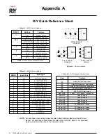
Страница 22: ...sor Lead 4 is open Lead 3 is open Lead 2 is open Lead 1 is open RTD Element 1 is open RTD Element 2 is open RTD Element 3 is open Table A3 LCD Displayed Problem Codes Input Type Pt 100Ω 385 RTD Pt 100Ω 3923 RTD Pt 100Ω 3916 RTD Pt 100Ω 3902 RTD Pt 200Ω 385 RTD Pt 500Ω 385 RTD Pt 1000Ω 385 RTD Pt 1000Ω 375 RTD 2 or 3 Pt 100Ω 385 RTD s Ave 2 Pt 100Ω 3923 RTD s Diff 2 Pt 100Ω 385 RTD s Diff 2 Pt 500Ω...

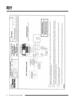
Страница 23: ...g the intrinsically safe option It also includes guidelines for setting up zener barriers necessary in these types of applications These diagrams must be used to augment the installa tion instructions earlier in this manual for units that are to operate in areas requiring intrinsically safe instru mentation Appendix B ...

Страница 24: ...RIY 22 The Interface Solution Experts ...

Страница 25: ...RIY The Interface Solution Experts 23 ...

Страница 26: ...OR BREACH OF ANY WARRANTY CONCERNING THE GOODS OR SERVICES SHALL BE FOR THE COMPANY AT ITS OPTION TO REPAIR OR REPLACE THE GOODS OR SERVICES OR REFUND THE PURCHASE PRICE THE COMPANY SHALL IN NO EVENT BE LIABLE FOR ANY CONSEQUENTIAL OR INCIDENTAL DAMAGES EVEN IF THE COMPANY FAILS IN ANY ATTEMPT TO REMEDY DEFECTS IN THE GOODS OR SERVICES BUT IN SUCH CASE THE BUYER SHALL BE ENTITLED TO NO MORE THAN A...

Отзывы: