LIN ENGINEERING
Page 1
Version 6.70
R701P User Manual
02/15/2022
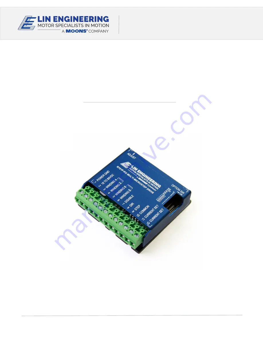
R701P
MICROSTEPPING DRIVER
USER MANUAL
VERSION 6.70
16245 VINEYARD BLVD, MORGAN HILL, CA 95037 TEL. 408.919.0200 FAX. 408.919.0201 WWW.LINENGINEERING.COM
Страница 1: ...INEERING Page 1 Version 6 70 R701P User Manual 02 15 2022 R701P MICROSTEPPING DRIVER USER MANUAL VERSION 6 70 16245 VINEYARD BLVD MORGAN HILL CA 95037 TEL 408 919 0200 FAX 408 919 0201 WWW LINENGINEER...
Страница 2: ...6 List of Parts 6 How to Connect 7 Optional 7 Resistor Values to set the Current 8 Resistor Values for the Opto Supply 9 7 CONFIGURING AND CONTROL OF THE R701P 10 Adjust Trimpot 10 Auto Current Reduct...
Страница 3: ...hes or between 0 Amps to 7 Amps when using the current resistor The power supply voltage must be between 4 times and 20 times the motor s rated voltage The current set resistor may be a Watt 5 part Fi...
Страница 4: ...negative side of your step pulses should then connect to your Step line Pin 9 The positive side of your 5V and the positive side of your step pulses should be tied together To disable the drive conne...
Страница 5: ...he bottom plate should not exceed 70 C For best results use heatsink compound between the R701P and the heatsink 4 MECHANICAL SPECIFICATIONS Size 2 5 x 2 5 x 0 838 63 5 mm x 63 5 mm x 21 3 mm Weight 3...
Страница 6: ...rement is depending on the image set 10 Opto Supply 5 VDC input used to supply power to the isolated logic inputs A resistor must be used if the supply is greater than 5 VDC 11 Current Set Connects to...
Страница 7: ...he motor may not run as smoothly as possible if it is too low and the board may be damaged if it is run too high Terminal 3 Phase A Terminal 4 Phase A Terminal 5 Phase B Terminal 6 Phase B Connect one...
Страница 8: ...4 usec Microstepping occurs on the falling edge of the step input Terminal 11 Current Set OPTIONAL Connect one end of the resistor to this terminal Terminal 12 Current Set OPTIONAL Connect the other...
Страница 9: ...into the optocouplers to 16 mA However if the supply is greater than 5 VDC then a resistor must be connected in series with the STEP line and another one in series with the DIRECTION line to maintain...
Страница 10: ...motor and power supply voltage The trimpot is located on the opposite side of main connector on the driver Auto Current Reduction The R701P reduces motor phase current to 70 of the set value when the...
Страница 11: ...LIN ENGINEERING Page 11 Version 6 70 R701P User Manual 02 15 2022 Option Set Switches...
Страница 12: ...res below for the corresponding motor NOTE The dots indicate the starting position of the wires when wound 4 Lead Wire Motor Connection Connect one set of windings to the A terminals Connect the other...
Страница 13: ...onnection Parallel Connection Eight wire motors can be connected in two ways Parallel and Series When in parallel the wires are simply connected such that the beginning of each winding are connected t...
Страница 14: ...ection with the sale of Lin Engineering products EXCEPT AS SET FORTH IN THE TERMS AND CONDITIONS AS SPECIFIED IN THE LICENSE AGREEMENT FOR THIS PRODUCT LIN ENGINEERING AND OR ITS AFFILIATES ASSUME NO...