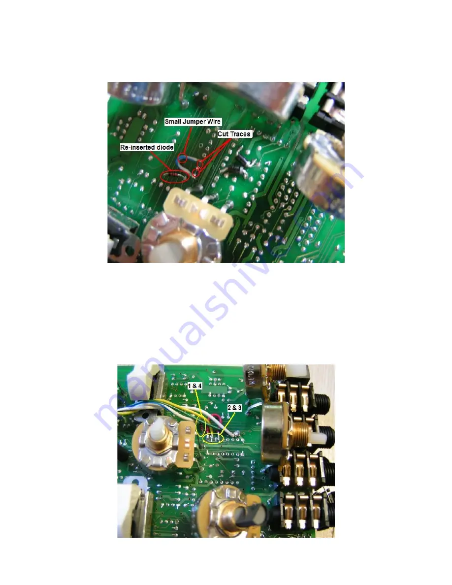
2. Locate the underside of chip U2 (gently bend the Drive pot back). Cut the traces that connect
pins 9 and 11 to pin 10 and attach an 8” wire to pin 10.
3. Jumper pins 9 and 11 of U2 back together with a small bit of wire (approx 1/2”). Measure the
resistance between pins 9, 10 and 11. Make sure 9 and 11 are shorted together and 10 is
isolated.
4. Attach an 8” wire to cathode side of D1.
5. Attach an 8” wire to empty cathode hole of D1. This is the hi/low 'N' control signal for
active/bypass.
6. Attach an 8” wire to pin 16 of U2.


