Page 2/3
Mounting and Installation Notes D765/9 (B97072-765-001; Version G, 02/15)
3 Installation
Compare model number and type with that specified on hy-
draulic schematic. The valve can be mounted in any position,
fixed or movable.
Mounting surface:
Check for flatness
(< 0.01 mm (0.00004 in) over 100 mm (3.94 in)) and finish
(R
a
< 0.8 µm). Care must be taken to ensure that contamina-
tion does not enter the hydraulic system, all work areas must
be clean of surface or air-borne contamination.
Mounting:
Socket head screws (grade 10.9) according to
EN ISO 4762, torque diagonally alternating.
4 Pilot Mode and Maximum Pressures
Pilot mode:
Pay attention to the hydraulic connection scheme
and to the mounting pattern of the hydraulic manifold. Pay at-
tention to the hydraulic schematic on the valve nameplate and
to the type designation defining the pilot mode.
Maximum pilot and operating pressure (p
X
, p
P
):
See name-
plate.
5 Electrical Connection
Electrical safety:
The protective conductor connection is con-
nected to the electronics housing or valve body. The insulation
materials employed are designed for use in the safety extra-
low voltage range.
To comply with safety regulations requires isolation from the
mains according to EN 61558-1 and EN 61558-2-6 and limiting
all voltages according to EN 60204-1. We recommend using
SELV/PELV power supplies.
Rated signal:
See nameplate.
External fuse per valve:
0.5 A medium time lag
Valve phasing:
A positive signal (D–E) causes valve opening
P
B.
Connector wiring:
See wiring schematic in the catalog or the
installation drawing.
Connection:
Signal lines shielded, shielding connected at
both ends and additionally connected to reference potential
(0 V) at the control side (to improve EMC). Connect the protec-
tive conductor.
Observe technical note TN 353.
Before applying electric signals the pilot stage has to be pres-
surized.
6 Hydraulic System Start Up
Pay attention to the pressure setting, the venting instructions
and the alarm messages!
7 Null Adjustment
Remove the locking screw with sealing ring from the motor cap
to access the null adjustment potentiometer. Turning the po-
tentiometer shaft results in a spool position change. Turning
clockwise will increase valve opening P
B(C2). The output
signal for actual spool position will also change. After adjust-
ment refit the sealing ring and the locking screw.
8 Maintenance
Except for a regular visual inspection for exterior leakage and
filter change, no maintenance work on the valves is required.
Changing the filter:
The installed filter protects internal ori-
fices and nozzles against coarse particle contamination. The
valve response time will increase as contamination increases.
The filters located below the filter cover at the side may be re-
placed by the customer.
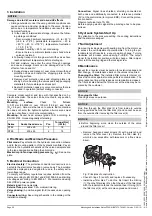
• Remove hexagon socket screws (5) with a wrench and
remove the filter cover (4). Remove the filter disk (2),
which is now accessible, with tweezers or a fine screw-
driver.
Fig.: Principles of construction
• Check O-rings (1) and (3) and replace if necessary.
• Install new filter disk. To do this, first insert the O-Ring
(1), then the filter disk (2) so that the side of the filter disk
with the indentation faces the outside. Insert O-ring (3) in
the filter cover (4) with some clean grease and mount.
NOTICE
Damage due to dirt, moisture and ozone/UV effects
• Storage outside or under the wrong climatic conditions can
cause corrosion and other damage to the valve. Conden-
sation due to temperature fluctuations can result in elec-
tronic malfunctions.
In the case of intermediate storage, observe the follow-
ing storage conditions:
• Recommended ambient temperature: +15 to +25 °C
(+60 to +78 °F), permissible temperature: –40 to
+80 °C (–40 to +176 °F), temperature fluctuation:
< 10 °C (18 °F)
• Relative humidity: < 65 % not condensing
• Ensure there are minimal vibration and shock where
valves are stored
Following transport or storage, wait until the valves have
reached ambient temperature before starting up.
• Dirt and moisture can enter the valve through openings
and cause damage. Seals can be damaged due to the
effects of ozone and UV.
During storage and transport, seal connectors with dust
protection caps and install the shipping plate on the
mounting surface.
Remove dust protection caps and shipping plate only
shortly before mounting the valves and keep packaging
materials for future storage and transport.
Seal with protection caps any valve connectors that are
not used in operation (without mating connector).
Series
Socket head screw
Pcs.
Torque [Nm]
(lbf in)
D765
M8 x 45
4
18
D769
M8 x 45
4
18
NOTICE
Changing the filter
Cleaning serves no purpose.
NOTICE
Fluid flow through the filter disk (2) is from inside to outside
leaving particles behind the filter disk (2) and cannot be seen
from the outside after removing the filter cover (4).
NOTICE
Before beginning work, clean the outside of the valve
around the filter cover!
4
5
3
2
1
©
199
9, 20
03,
20
08,
2
009,
2010
Moo
g
G
m
bH,
Hann
s-
Klemm-S
tr
.
28,
7103
4
B
öblin
gen,
GERMA
N
Y
, www.moo
g
.c
om
/in
dustr
ial
A
ll rig
h
ts reserved
. Sub
ject t
o
c
hange
s.

